WHITE PAPER
A Guide to Successful Installation of Power over Ethernet
Download PDF
Overview
Years ago, someone conceived the idea of delivering low-voltage direct current (DC) power and data simultaneously over twisted pair network cabling, and Power over Ethernet (PoE) was born. Since its inception in 2003, PoE technology has evolved to offer more power and support an ever-expanding range of networked IP-based powered devices — from VoIP phones, surveillance cameras, and Wi-Fi access points (APs) to LED lights, laptops, and digital displays. Successful implementation and troubleshooting are crucial to realizing the benefits of this modern power delivery method.

On This Page
How PoE Works
For networked devices, PoE eliminates the need for traditional alternating current (AC) power circuits and outlets. It utilizes efficient low-voltage 43 to 57 VDC over twisted-pair network cabling, such as Category 6A, Category 6, and Category 5e. This means PoE can be installed without risk to safety and with fewer strict requirements compared to traditional AC line-powered devices, such as the need for a certified electrician, conduit, and electrical boxes, resulting in reduced labor and material costs.
What Is a PoE Circuit?
A PoE circuit is made up of three parts:
- Power Sourcing Equipment (PSE), which injects power over the same cabling as the data signals. This is typically a PoE-enabled network switch but can also be a midspan injector used in instances where the switch is not capable of supplying power.
- Twisted-pair network cable, which carries both power and data signals. The IEEE standards for PoE specify power delivery over two or four pairs of a four-pair twisted cabling system.
- Powered Device (PD), which consumes the power provided by the PSE.
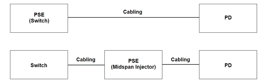
Figure 1. Basic PoE design and nomenclature.
Current Standards for PoE
IEEE 802.3 standards define how PDs receive power from the PSE. In a PoE system, power is sourced by the PSE only after the PD requests it. This is part of a process referred to as negotiation, which involves the PSE discovering if a connected device is PoE compliant and delivering only the amount of power the device needs to operate. If the PD is disconnected, the PSE immediately removes power, making PoE considerably safer than typical AC power, which is always present at the outlet.
The first PoE standard, IEEE 802.3af, was adopted in 2003 and sourced up to 15.4 watts (W) of power over two pairs. Then, adopted in 2005, IEEE 802.3at (also known as PoE+) was adopted in 2005; it supported up to 30 W. Two years later, Cisco developed its Universal PoE (UPOE) using all four pairs, pushing the maximum power to 60 W. In September 2018, the IEEE approved 802.3bt, enabling up to 60 W and 90 W of sourced power.
Figure 2 shows the IEEE PoE standards defined by eight different wattage levels or classes, which can be delivered via four configurations: Type 1 and Type 2, which use two pairs, and Type 3 and Type 4, which use four pairs.
|
Figure 2: PoE classes, types, and standards. |

Three Steps to Successful PoE Implementation
PoE implementation is a three-step process:
- Equipment selection
- Cable certification
- Installation and troubleshooting
Let's look at what's required in each step.
Step 1: Equipment Selection
Although PoE provides significant benefits, standardization is essential. The term PoE itself is not a trademark. Any vendor can claim PoE capabilities. And vendors have adopted additional terms such as “PoE+” and” PoE++,” as well as Cisco's Universal PoE (UPOE).
While these approaches all comply with the three IEEE standards, vendors also create confusion with other PoE implementations that fall outside the standards. For example, "passive" PoE implementations provide "always on" power, which is not negotiated between the PSE and PD. Other implementations negotiate power levels in higher layers than the Link Layer Discovery Protocol (LLDP), which is used by equipment and devices to advertise their capabilities.
Techs in the field — and even designers — can quickly become confused about what will work with what. Not surprisingly, a recent study of over 800 installers, integrators, and end users found that four out of five respondents experienced difficulties in integrating PoE systems.
Ethernet Alliance Certification Program
To cut through this confusion and enhance interoperability, the Ethernet Alliance — a consortium of manufacturers of PSE switching equipment, PDs, and testing solutions — developed a PoE Certification Program. This program provides a methodology for manufacturers to certify their products for interoperability with other IEEE 802.3-based PoE solutions and offers simple labeling for such products.
Certification of the products is defined by a 300-page test plan, using approved equipment. Certification testing may be conducted by manufacturers or third parties, such as the University of New Hampshire's Interoperability Laboratory (UNH-IOL). Both PSE and PD equipment may be certified. Equipment that passes this rigorous process may be labeled with the EA-approved marks as shown below.
Designers or installers of PoE equipment can simply compare the marks on the PSE and PD to determine compatibility. If the rating of the PSE is equal to or higher than the requirements of the PD, functionality is assured.
 |
Figure 3. Ethernet Alliance marks for Powered Devices (left) and Power Sourcing Equipment (right).
Step 2: Cable Certification
PoE is designed to run over standard Category 6A, 6, and 5e twisted-pair structured cabling. However, adding DC power to a cable carrying high-speed data places some additional requirements on the cabling.
- The overall resistance of the cable must be low. If it's too high, the power will dissipate between the PSE and the PD, and the PD won't receive adequate power.
- PoE is transmitted by applying a common-mode voltage on two or four pairs, meaning the current is evenly split between the two or four conductors. For this to happen, the DC resistance of each conductor in the pair must be balanced (equal), and any difference is referred to as DC resistance unbalance. Excessive DC resistance unbalance can distort data signals, causing bit errors, retransmissions, and even nonfunctional data links.
- In Types 3 and 4, PoE implementations which deliver power over all four pairs of a category cable, it is no longer just the DC resistance unbalance on each pair you need to worry about. Excessive DC resistance unbalance between multiple pairs can also wreak havoc on data transmission or cause PoE to malfunction.
The IEEE has recognized the importance of these resistance measurements and has included requirements for DC loop resistance and DC resistance unbalance within a pair in the 802.3 standard. The Telecommunications Industry Association (TIA) has also specified these parameters in ANSI/TIA-568.2 cabling standards for Category 5e, 6, and 6A cabling channels.
Unfortunately, most installations are certified using the field-testing standard TIA-1152-A, which defines these measurements as optional. Inferior terminations, where individual conductors are not properly and consistently seated within IDCs can cause DC resistance unbalance. So while you may see a DC resistance unbalance specification on a vendor's cable, field testing is really the only way to ensure DC resistance unbalance performance after installation.
Using a cable certification tester that includes these resistance measurements as a default (such as the Fluke Networks DSX CableAnalyzer™ Series) allows you to quickly and easily test DC resistance unbalance within a pair and between pairs, so you can rest assured that the cable plant you deploy will perform in two- and four-pair PoE applications. Certification testing is also typically required to acquire a warranty on the cable plant, and it facilitates future troubleshooting. The DSX CableAnalyzer Certifier lets you store and manage results and generate reports via LinkWare™ PC management software or LinkWare™ Live cloud-based service, which enables you to upload results from the job site.
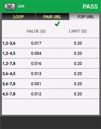
Figure 4. Versiv display of pair-to-pair resistance unbalance results.
Step 3: Installation and Troubleshooting
Knowing the capacity of the PSE and the requirement of the PD makes installation and troubleshooting much simpler.
Unfortunately, in the real world, technicians supporting PoE-powered devices often lack access to this information. They can easily check the requirements of an EA Certified PD, but they are typically working quite some distance from the PSE — which means a long walk back to the telecommunications closet or data center to determine the capabilities of the switch. They are also often faced with figuring out which cable goes to their PD. In some instances, they may not even have access to the PSE and would need to contact the IT team to determine its capacity. A tech could waste half a day tracking the cable and accessing the switch.
Tools Designed to Solve PoE Problems
Fluke Networks has developed two tools to solve these problems and save technicians hours of frustration: the LinkIQ™ Cable+Wi-Fi+Network Tester and the MicroScanner™ Cable Verifier. Simply plug either tool into the cable, and if it's connected to a PSE, it will display the wattage and class (0-8) of power available on the link and indicate which pairs are carrying power. The tech can then compare that to the requirements of the PD and know if sufficient power will be available. Both products have successfully completed the Ethernet Alliance Gen2 PoE Certified program test plan, providing confidence that it will work with all IEEE-compliant devices. The tester is also designed to work with a wide variety of non-IEEE-compliant technologies.
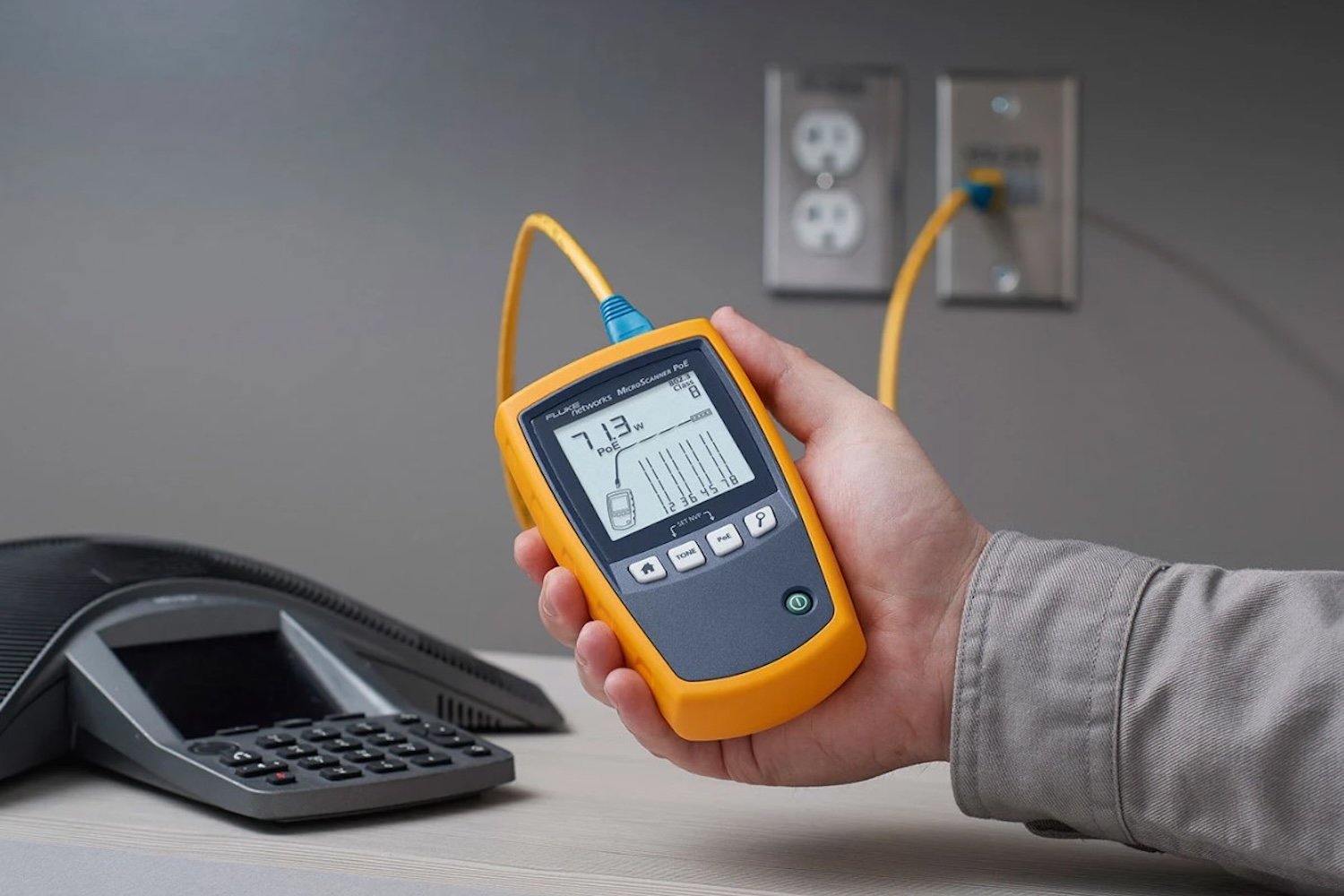
Figure 5. The Ethernet Alliance PoE-certified MicroScanner Cable Verifier displays the wattage and class (0-8 of power available on the link and indicates which pairs are carrying power.
The LinkIQ tester takes PoE testing even further by displaying the actual negotiated PoE class and wattage available from the PSE at both the hardware and software levels, ensuring PDs can both receive power from the switch and efficiently negotiate for dynamic power allocation. The LinkIQ tester performs an additional test by placing a load on the connection and measuring the voltage per port in real-time to verify if the switch and cable link are capable of delivering the advertised power. This is ideal for testing live PoE networks where PoE-enabled switches allocate power to each port based on the requirements of its connected devices. If multiple devices are powered, your switch may not have enough available power for a new PD.
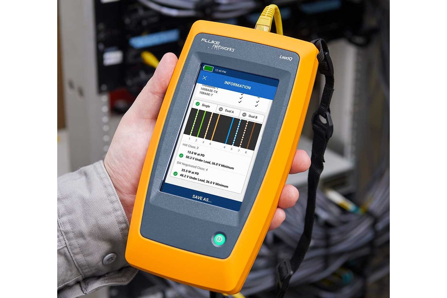
Figure 6. The Ethernet Alliance PoE-Certified LinkIQ tester displays negotiated PoE class and wattage from the PSE at both the hardware and software levels and performs PoE load testing to measure voltage sourced by the port to verify proper operation.
The LinkIQ and MicroScanner testers are invaluable to techs in other ways as well. They identify the port speed up to 10 Gbps, which is helpful information, as a slow port may limit the performance of a Wi-Fi AP, camera, or other high-speed device. If the cable is damaged, the testers display the length of each pair, potential breaks, or other failures. The LinkIQ and MicroScanner testers can even serve as a tone source for tracing cables with the Fluke Networks IntelliTone™ 200 Pro Probe, which helps locate cables in walls, in bundles, or at switches, patch panels, or wall outlets.
The LinkIQ tester provides additional features to aid in troubleshooting the network. It displays the switch's name, its advertised speed, the specific port number, and the virtual LAN (VLAN) assigned to a link. You can even identify the connected switch port using the LinkIQ Duo tester's Blink Port Light feature and perform an IP ping test to confirm whether links can reach a specific target address and determine latency.
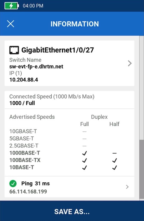
Figure 7. The LinkIQ tester displays the switch's name, its advertised speed, the specific port number and virtual LAN (VLAN) assigned to a link, and performs an IP ping test.

Figure 8. The LinkIQ Duo tester shows details of the wireless Access Point, including name, networks supports, band used, technologies, and signal strength.
The LinkIQ tester is also available as the LinkIQ Duo model, which adds Wi-Fi analysis to Wi-Fi 6E. Most Wi-Fi APs are PoE enabled, and the LinkIQ Duo tester lets you troubleshoot both PoE and Wi-Fi with a single tool. It makes analyzing your Wi-Fi environment easier by running a complete suite of tests and displaying the results the way you want to view them — by networks, channels, or access points. And the LinkIQ tester can generate reports and store or print them using the popular LinkWare PC software.
|
|
|||
|
Cable Troubleshooting |
X |
X |
X |
|
Cable Performance Tests |
|
10 Mb/s to 10 Gb/s |
Certification to TIA, ISO and International Standards |
|
Resistance Measurements for PoE |
|
|
X |
|
Switch Port Speed Identification |
X |
X |
|
|
Switch Tests (Name, Port, VLAN) |
|
X |
|
|
PoE Port Testing |
X |
X |
|
|
Loaded PoE Port Test |
|
|
|
|
Wi-Fi Analysis and Testing |
|
X |
|
|
Reporting |
|
Figure 8. Comparison of Fluke Networks tests for PoE devices and cabling.
Make your PoE projects run smoothly by selecting the right equipment, certifying the cable, and ensuring that your technicians have the correct testers to easily check and troubleshoot the installation.
Keep Learning
- Three Reasons Cabling Certification Is More Important Than Ever
- DC Resistance Unbalance: What You Need to Know
- White Paper: DC Resistance Unbalance Testing: Easy, Low-Cost Insurance for Your PoE Systems
- What is (+All) and When Should I Choose It?
- To Bundle or Not Bundle?
- What You Need to Know to Choose a PoE Tester
- PoE Load Testing: Advanced Troubleshooting for Your PoE Systems
- How to Test if Your Ethernet Cables Support PoE
- LinkIQ Duo: Cable, PoE, Wi-Fi, and Network Testing All in One Device
- How to Simplify Wi-Fi Analysis with LinkIQ™ Duo
- Ethernet Alliance PoE Certification: MicroScanner™ PoE


