The OM Mantra
May 22, 2020 / General, Standard and Certification, Industrial Networks
Adopted by TIA, the nomenclature for multimode fiber found in the ISO/IEC 11801 standard includes the prefix “OM.”
Rather than the spiritual mantra you hear in yoga class, most sources in our industry state that the acronym OM comes from “optical multimode” which seems rather obvious. But when it comes to the various nuances of each type of OM, the differences aren’t quite as obvious.
Let’s take a closer look.

Core Curriculum
There are currently five types of OM fiber—OM1, OM2, OM3, OM4 and OM5. OM1 fiber was the de facto choice for fiber throughout the 1980s and 1990s, and was still installed into the early 2000s. OM1 has a core diameter of 62.5 µm while OM2, OM3, OM4 and OM5 all feature a 50 µm core.
While the light carrying core of OM1 has a different diameter, all the OMs have the same sized glass cladding of 125 µm. That means that the overall outer diameter is the same across all OMs, and they are equally strong and handled identically during installation. So what does different core size mean?
OM1 fiber’s larger core size is optimized for use with LED-based light sources commonly found in slower-speed legacy systems. The smaller 50 µm core size offered greater bandwidth for use with laser light sources, but OM2 fiber never gained widespread use since lasers were too expensive and LEDs remained the primary light source at that time. And then OM2 really lost its chance to shine once lower cost 850-nm vertical-cavity surface-emitting lasers (VCSELs) were introduced.
Change Your Profile
Because VCSELs cause greater differential mode delay (DMD) that adversely impacts bandwidth, fiber manufacturers changed the refractive index profile of 50 µm fiber to help minimize DMD and maximize bandwidth (in case you missed it, check out this previous blog that explains DMD). The change in profile gave us OM3 laser-optimized 50 µm fiber and the subsequent demise of OM2 in the early 2000s. Notice in the table that OM1 and OM2 are not specified for effective laser launch bandwidth achieved with 850nm VCSELs.
As with every technology, manufacturers are always seeking to make things better—and in the case of signal transmission, it’s all about making things faster. So not long after OM3 was introduced, fiber manufacturers figured out how to alter the refractive index profile to further reduce DMD, and in August of 2009, TIA/EIA approved and released performance criteria for OM4.
The main benefit to reducing DMD is better modal bandwidth – the lower the modal dispersion, the higher the bandwidth. OM4 provides a higher modal bandwidth than OM3 – 4700 MHz*km compared to 2000 MHz*km – and that means OM4 can transmit more information within the same distance or the same amount of information for longer distances (yup – we had a blog on modal bandwidthtoo).
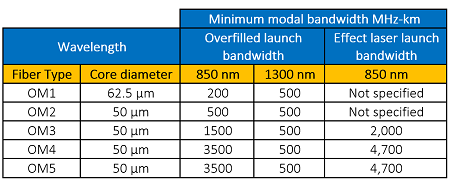
Notice that OM4 and OM5 have the same bandwidth and performance values. The main difference between OM4 and OM5 is that OM5 is designed to be used at wavelengths beyond 850 nm, specifically 880 nm, 910 nm and 940 nm. This means that it can support four simultaneous transmissions with wave division multiplexing (WDM) technology (and if you thought for one second that we didn’t have a blog on OM5, think again).
What Really Matters
While understanding core sizes, light sources, DMD and modal bandwidth gives you some technical insight into the construction and performance of the OMs, what most want to know is what applications they support.
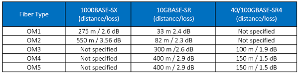
This table shows the common fiber-based Ethernet applications and distances supported for each OM, as well as the associated loss limit – both distance and loss need to be considered for the application to work.
So when certifying your multimode fiber plant with your Fluke Networks’ CertiFiber® Pro, make sure to choose both your fiber type and your application.
Recent Posts See All >
What Is PoE Negotiation?
2025-06-30
More General Posts See All >
MPOs in the Data Center and How to Test Them
2025-11-18
Explore Our Products
CertiFiber® Pro Optical Loss Test Set


