Navigating Ultra-High-Density 400 and 800 Gig Networks in AI Data Center Environments
October 6, 2025 / General, Installation and testing, Best Practices
Artificial intelligence (AI) is rapidly transforming the data center. From training large language models (LLMs) like ChatGPT to delivering personalized content and predictive analysis, hyperscalers, cloud providers, and large enterprises are building high-performance computing (HPC) networks that leverage accelerated parallel processing to unlock AI's potential. Let's look at how these AI networks are deployed and the cable testing challenges they present.
|
|

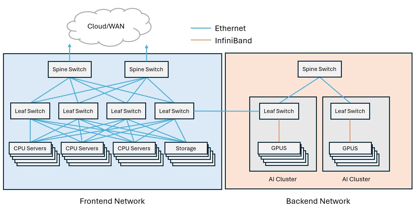
The Two Sides of AI Networking: Backend and Frontend
AI in the data center relies on two distinct networking approaches: the backend for intensive training and the frontend for real-world inference. During training, AI models learn to recognize patterns, make predictions, and draw conclusions by analyzing massive data sets across interconnected high-performance Graphical Processing Units (GPUs) in an AI cluster or GPU fabric. This computationally demanding process requires high-bandwidth, low-latency data transfer between GPUs for efficient model training and faster insights.
Once an AI model is trained, inference is when it is put into action, responding to user queries and drawing conclusions from new information. This process is significantly less computationally intensive. Think of an identification app for dog breeds: Training is when the AI model learned to recognize breeds of dogs by analyzing tens of thousands of labeled images, while inference is when the model identifies a new image of a dog that you send it.
Compute-intensive training within AI clusters occurs in a backend data center network, a dedicated, closed environment designed to facilitate rapid GPU data transfer and processing. In contrast, the frontend network connects AI systems to the outside world for inference, handling user requests alongside other general-purpose data center workloads (such as web hosting, email, and storage). These two networks work together to manage data transfer, storage, and user interactions.
Frontend and backend network architectures have some differences:
- • Frontend networks employ traditional three-tier or leaf-spine Ethernet architecture, incorporating various functional areas for service provider demarcation, switch layers, storage devices, and basic CPU-based servers. Switch-to-switch connections here typically use single-mode or multimode fiber with multi-fiber MPO connectivity for 100 to 400 Gig, while switch-to-server links tend to be 25 to 100 Gig via duplex multimode fiber.
- • Backend networks almost exclusively use leaf-spine architecture, where leaf switches (sometimes called rail switches) provide high-bandwidth, low-latency GPU interconnectivity within a cluster and spine switches provide connectivity between multiple clusters. Switch-to-switch connections in the backend today are primarily 800 Gig, requiring 16-fiber MPO connectors (8 fibers transmitting and 8 receiving at 100 Gb/s). Some hyperscalers and large cloud service providers are already transitioning to 1.6 Terabit switch connections in the backend using two 16-fiber MPO connectors.
GPUs in backend networks typically connect at speeds of 400 Gig, requiring 8-fiber MPOs (4 fibers transmitting and 4 receiving at 100 Gb/s), with some GPU connections moving to 800 Gig. Unlike the Ethernet-dominated frontend network, GPU interconnects in the backend frequently leverage the InfiniBand protocol with Remote Direct Memory Access (RDMA) technology for reduced latency. RDMA over converged Ethernet (RoCE) is an emerging alternative that combines the best of both protocols.
To further minimize latency, GPUs often connect directly to their leaf switch, eliminating the use of structured cabling (interconnects and cross-connects) to manage equipment connections. These direct connections use pre-terminated MPO fiber assemblies or direct-attach twinax or optical assemblies. A single AI cluster can contain hundreds of GPUs that consume up to 10 times more power than CPUs. This leads to much higher heat generation, requiring data centers to invest in more advanced cooling technologies, like liquid cooling, for these cluster environments.
|
|
Challenges in Testing AI Infrastructure in Data Centers
Interconnecting hundreds of GPUs at speeds of 400 Gig or higher in backend AI clusters results in extremely high fiber densities in data centers, which presents some unique challenges when it comes to testing and troubleshooting.
-
Inspecting fiber end faces for contamination is crucial to prevent signal loss and reflections that degrade performance, but inspecting ports in ultra-high-density environments can be difficult. The Fluke Networks FI-3000 FiberInspector™ Ultra Camera offers a solution with PortBright™ illumination for visibility in dense environments, plus AutoFocus/AutoCentering for instant live view of fiber end faces, including easy zoom for inspecting individual fiber end faces or an entire MPO array. The FI-3000 FiberInspector Ultra Camera comes standard with tips for inspecting 12- and 24-fiber UPC/APC MPO end faces, with optional tips for MMC and keyless MPO APC tips for 12 to 32 fibers.
If inspection reveals the need to clean MPO or MMC interfaces, Fluke Networks has Quick Clean™ Cleaners to effectively remove contaminants from bulkhead MPO/MTP and MMC connector end faces, as well as various duplex connectors.
|
The Fluke Networks FI-3000 FiberInspector™ Ultra Camera and Quick Clean™ MPO/MTP and MMC Cleaners are ideal for inspecting and cleaning fiber end faces in high-density data center environments like AI clusters. |

- Insertion loss testing for high-speed 400 Gig Ethernet or InfiniBand fiber links in backend networks should be done using a tester with an onboard MPO connector, like the Fluke Networks MultiFiber™ Pro MPO tester, that can scan all fibers simultaneously and display loss results for the entire link. The MultiFiber Pro tester also tests MPO links for correct polarity, which is essential to ensure that each transmit fiber corresponds to its receive fiber. Testing 16-fiber MPOs used in 800 Gig links currently requires a Y breakout cable (16-fiber MPO connector to two 8-fiber fiber MTP/MPOs). Each 8-fiber leg is tested, and the results are combined to determine overall link loss.
- Very small form factor (VSFF) fiber connectors — such as MDC and SN-MT duplex connectors and MMC array connectors, which offer multiple times the density of traditional connectors — are becoming common in high-density AI clusters. Fluke Networks offers industry recommended 1-jumper reference for MDC connectors now and will develop similar methods for other VSFF connector types as they are more widely adopted. Until then, testing can be done with a 3-jumper reference method. The Fluke Technical Assistance Center (TAC) can provide guidance on testing new VSFF connectors.
|
The Fluke Networks FiberLert™ Live Fiber Detector detects active fiber signals at QSFP transceiver ports. |
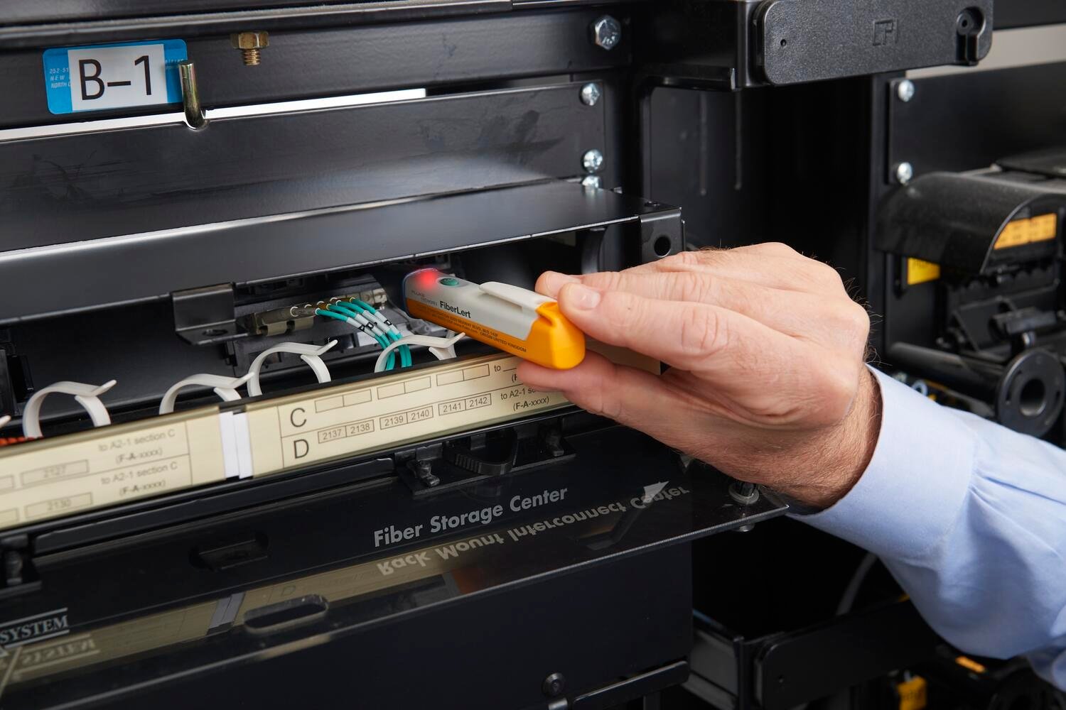
- Troubleshooting QSFP transceivers is often necessary when there's a problem in an AI network. You can use the FiberLert™ live fiber detector from Fluke Networks in a multimode or single-mode transceiver port to quickly and safely confirm fiber activity and connectivity. Its small size fits easily into access high-density switch ports. When you need more in-depth troubleshooting, the Fluke Networks OptiFiber™ Pro OTDR can pinpoint and measure signal loss and reflectance of specific events (connectors, breaks, bends, etc.).
The integration of AI into the data center will continue to drive significant evolution in network cabling architectures, and the resulting higher densities will present ongoing challenges for data center operators. As the industry continues to push the boundaries of AI capabilities, robust and efficient testing and troubleshooting solutions will be crucial to ensure reliability and performance in these 400 Gig+ networks.
Keep Learning
- • Download our e-book: Fiber Testing Best Practices for Today's Data Centers
- • What You Should Know About VSFF Connectors
- • Learn more about Multi-fiber Push On (MPO) Connectors
- • Easier Fiber End Face Inspections: Key Changes to IEC 61300-3-35
- • Check out our Guide to Fiber Optic Testers, Tools, and Troubleshooting
Recent Posts See All >
What Is PoE Negotiation?
2025-06-30
More General Posts See All >
MPOs in the Data Center and How to Test Them
2025-11-18


©2006-2021 Fluke Corporation。保留所有权利。
RM2011, 20/F, SCITECH Tower, 22 Jianguomenwai Avenue, Chaoyang District, Beijing, China
地址:北京市朝阳区建国门外大街22号赛特大厦20层2011室
联系电话:400-8103435
沪ICP备11037028号-15![]()