OM1, OM2, OM3, OM4, OM5 and OS1, OS2 Fiber
In ANSI/TIA-568.3-D, the TIA adopted the nomenclature for fiber found in the international standard ISO/IEC 11801. The multimode fiber is prefixed with “OM” and the singlemode mode “OS”.
The new designation in ANSI/TIA-568.3-D should alleviate some of the confusion associated with application support distance issues. Each “OM” has a minimum Modal Bandwidth (MBW) requirement.
|
|
|
Minimum modal bandwidth MHz-km |
||
|
Wavelength |
Overfilled launch bandwidth |
Effect laser launch bandwidth |
||
|
Fiber Type |
Core diameter |
850 nm |
1300 nm |
850 nm |
|
OM1 |
62.5 µm |
200 |
500 |
Not specified |
|
OM2 |
50 µm |
500 |
500 |
Not specified |
|
OM3 |
50 µm |
1500 |
500 |
2,000 |
|
OM4 |
50 µm |
3500 |
500 |
4,700 |
| OM5 | 50 µm | 3500 | 500 | 4,700 |
Why two values? What’s the difference between overfilled and effective? Overfilled is with an LED source, effective is with a VCSEL. New vs old. Loss length testing to ISO/IEC must be done with an LED and should be done with an LED for TIA testing to avoid optimistic results.
To most users, the following table may be of more benefit:
|
|
1000BASE-SX |
10GBASE-SR |
40GBASE-SR4 |
100GBASE-SR10 |
|
OM1 |
275 m |
33 m |
Not specified |
Not specified |
|
OM2 |
550 m |
82 m |
Not specified |
Not specified |
|
OM3 |
Not specified |
300 m |
100 m |
100 m |
|
OM4 |
Not specified |
400 m* |
150 m |
150 m |
| OM5 | Not specified | 400 m* | 150 m | 150 m |
* The IEEE in conjunction with the TIA is supporting 10GBASE-SR to 400 m over OM4.
Cautionary note: In ANSI/TIA-568-B.3, the modal bandwidth of 62.5 µm fiber was 160 MHz.km, not the 200 MHz.km found in the current ANSI/TIA-568.3-D. This change was done to harmonize with ISO/IEC 11801. That would reduce the distance for 1000BASE-SX to 220 m and 10GBASE-S to 26 m.
There is also a loss limit associated with these distances too.
|
|
1000BASE-SX |
10GBASE-S |
40GBASE-SR4 |
100GBASE-SR10 |
|
OM1 |
2.60 dB |
2.4 dB |
Not specified |
Not specified |
|
OM2 |
3.56 dB |
2.3 dB |
Not specified |
Not specified |
|
OM3 |
3.56 dB |
2.6 dB |
1.9 dB |
1.9 dB |
|
OM4 |
Not specified |
2.9 dB |
1.5 dB |
1.5 dB |
| OM5 | Not specified | 2.9 dB | 1.5 dB | 1.5 dB |
So in your design, you have to take into account BOTH distance and loss to ensure your application will work. OM4 fiber needs a reduced fiber loss in order to support 100GBASE-SR10 to 150 m.
|
|
850 nm |
1300 nm |
1310 nm |
1550 nm |
|
OM1 |
3.5 dB/km |
1.5 dB/km |
|
|
|
OM2 |
3.5 dB/km |
1.5 dB/km |
|
|
|
OM3 |
3.0 dB/km |
1.5 dB/km |
|
|
|
OM4* |
3.0 dB/km |
1.5 dB/km |
|
|
| OM5 | 3.0 dB/km | 1.5 dB/km | ||
|
OS1 ISP |
|
|
1.0 dB/km |
1.0 dB/km |
|
OS1 OSP |
|
|
0.5 dB/km |
0.5 dB/km |
|
OS2 ISP |
|
|
1.0 dB/km |
1.0 dB/km |
|
OS2 OSP |
|
|
0.5 dB/km |
0.5 dB/km |
ISP = Inside plant, OSP = Outside plant (Applicable to TIA only)
While OM5 has similar performance values to OM4 for Insertion Loss and Distances supported, it has a special characteristic that differentiates it. OM5 fiber is designed to be used at wavelengths beyond 850 nm, specifically, 880 nm, 910 nm, and 940 nm. This means that it can support four simultaneous transmissions with Wave Division Multiplexing. There is an attenuation value for the 953 nm wavelength, 2.3 dB per KM. Field testing of OM5, however, only needs to be done at 850 and 1300 nm wavelengths.
* The values above for OM4 are taken from TIA-492AAAD. This is a minimum requirement. Some vendors are quoting 2.3 dB/km. Check with your vendor and work with them carefully on the design of the fiber plant.
IMPORTANT:
When you setup your DSX CableAnalyzer Cable Type for fiber,
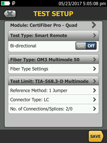
it is important to make sure you select the fiber with the correct modal bandwidth. It will not affect the outcome of your TIA or ISO/IEC loss length test, but it will affect what shows up at the bottom of the test report in LinkWare for Network Compliant Standards.
Related Resources
- Free Pocket Guide: Fiber Testing Best Practices
- ANSI/TIA-568.3-D testing may not guarantee your fiber application works. Learn More
- Commscope Link Loss Calculator – How To Guide Learn More
- New Loss Budget Values for Reference Grade Connectors in ANSI/TIA-568.3-D Learn More
- Test reference cords (TRCs) vs. patch cords Learn More
- Learn More about Fiber Testing
Related Products
FI-500 FiberInspector™ Micro
FI-7000 FiberInspector™ Pro

Fiber Optic Cleaning Kits


