Short-Reach Single-Mode Data Center Applications Put Reflectance on the Radar
October 15, 2025 / General, Installation and testing, Upgrading and troubleshooting
Most of us understand that insertion loss is a critical parameter for fiber applications, especially in multimode applications with stringent loss budgets. While insertion loss has historically been less of a concern in long-reach single-mode applications, that’s no longer the case with short-reach single-mode applications, which have reduced loss budgets that also depend on reflectance.
|
|

Strict Insertion Loss Budget
Insertion loss requirements and link lengths in multimode applications have gotten stricter with increasing speeds. The maximum insertion loss for 10 Gig over 400 meters of OM4 multimode (10GBASE-SR) is 2.9 dB. For 400 Gig over 100 meters of OM4 multimode (400GBASE-SR4), the maximum insertion loss is just 1.8 dB. In contrast, long-reach single-mode applications have much larger loss budgets — 6.3 dB for 10-kilometer applications (LR) and between 15 and 18 dB for 40-kilometer applications (ER). However, newer short-reach single-mode applications (DR and FR) have insertion loss budgets that are more in line with multimode applications. And it’s not just insertion loss that matters with these applications; you now need to also be concerned with reflection.
Short-reach single-mode applications are increasingly popular for data center links that require more than the 100-meter distance supported by multimode fiber but do not necessitate the distances of long-reach single-mode applications that use expensive, high-power laser transceivers. Instead, short-reach single-mode applications use lower-cost, low-power transceivers to support distances of 500 meters or 2000 meters. These cost-effective applications come with reduced insertion loss allowances as shown in the table below.
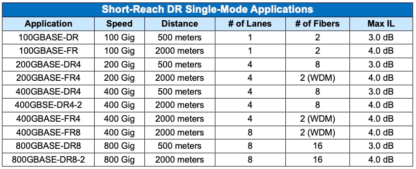 |
With these lower insertion loss limits, multiple connections could pose a problem. When selecting single-mode connectivity, designers must now consider insertion loss and choose low-loss components to stay within budget. A standard 0.75 dB connector will no longer suffice. (If you do the math, it’s easy to see that four 0.75 dB connectors and the loss of your cable will put you over budget in a short-reach DR channel.)
Not only do you need to be aware of the reduced loss budget with these new short-reach single-mode applications, but you also need to be concerned with reflectance. In fact, insertion loss limits for these applications depend on reflectance.
Reflectance and Why It Matters for Short-Reach Single-Mode
Before we discuss why reflectance is a concern in short-reach single-mode applications, let’s take a step back and review reflectance.
Reflectance measures the amount of signal power reflected from a connector or end of the cable back toward the transceiver compared to the amount of signal power injected. It is always a negative value. Reflectance is essentially the reverse of return loss, which measures the signal power injected compared to the amount that is returned or reflected and is always a positive value. For both reflectance and return loss, values farther away from zero are better. (See more details in Insertion Loss Should Be a Positive Number.)
At a fiber connector, a small air gap exists between the two fibers. The difference in refractive index between the glass and air causes light to be reflected. Reflectance can also be caused by contaminated or poorly polished end faces, core misalignments, cracks in the fiber, open fiber ends, and manufacturing impurities.
While multimode transceivers are highly tolerant of reflection, single-mode transceivers are not — especially at higher wavelengths. In fact, with high-power single-mode lasers, excessive reflection can actually damage the transceiver. That is why APC connectors are commonly used in long-reach single-mode applications. APC connectors have an 8-degree angled end face that reflects light back into the cladding rather than straight back toward the transceiver, offering better reflectance (and return loss). Note that while it is possible to achieve good reflectance with a UPC LC connector, all multi-fiber MPO single-mode connectors are APC because it’s impossible to achieve the required reflectance on an MPO with a straight UPC end face.
A New Reflectance Requirement
While single-mode transceivers have always been susceptible to reflectance, the low-cost, low-power transceivers used in short-reach single-mode applications are even more sensitive to reflectance. The TIA 568.3 fiber optic cabling standard specifies connector return loss (positive), but it does not require it for Tier 1 testing. However, IEEE 802.3 Ethernet application standards specify reflectance (negative). In addition, OTDRs required for Tier 2 testing report reflectance — not return loss.
For short-reach single-mode applications, IEEE specifies reflectance based on the number of mated pairs in the channel. If the reflectance values cannot be met, the maximum channel insertion loss must be reduced, fueling the case for APC connectors. As shown in the table below, if the reflectance value of mated connectors is -37 dB, you can have only one connector in a short-reach single-mode channel. With an improved reflectance value of -49 dB, you can have 10 connectors in the channel.
|
|

To determine maximum channel loss, IEEE specifies insertion loss versus the number of discrete reflectances as shown in the table below.
|
|

- • In a 400GBASE-DR4 application with four connectors that have a reflectance value of -50 dB and no connections between -35 and -45 dB, the insertion loss is 3.0dB (highlighted in red in the table).
- • If the reflectance of those same four connectors is -40dB, the maximum insertion loss goes down to 2.7dB (highlighted in yellow in the table).
- • Remember that values further away from zero are better for reflectance.
What Should You Design To?
Since most single-mode LC and MPO connectors have a good reflectance of about-55 dB, it might seem that you could easily design your channel with an insertion loss of 3.0dB. But wait: Reflectance can worsen over time as dirt and debris settles on connector end faces due to normal day-to-day insertions and removals of jumpers. Just because the connectors had a reflectance of -55 dB on day one does not mean they will remain at -55 dB forever. Dirt and debris on fiber end faces is especially a concern in single-mode connectors, where the fiber core is much smaller — it’s easier to block more light with a tiny dust particle on a small 9-micron single-mode fiber core compared to a larger 50-micron multimode fiber core.
Even if connectors measure -55dB reflectance in Tier 2 OTDR testing on day one, you’d be wise to build in some margin due to the potential for increased reflectance down the road. In the case of four connectors in a short-reach single-mode application, this might mean designing to 2.7 dB rather than 3 dB.
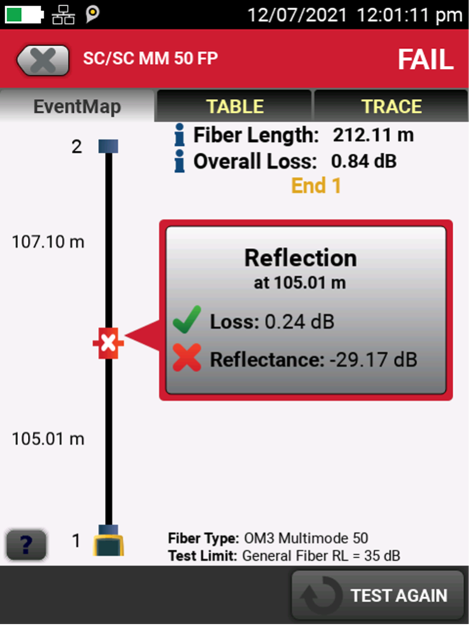
It’s essential to note that even if your link passes Tier 1 (insertion loss) testing with a substantial margin, excessive reflectance can still render the link inoperable. That’s where an OTDR such as the Fluke Networks Fluke Networks OptiFiber™ Pro comes in — it’s the only way to accurately measure the reflectance of connections. OptiFiber Pro even automatically interprets the results and displays the detailed reflectance of all connections on an intuitive graphical EventMap.
|
CertiFiber Pro displays reflection values on an intuitive graphical EventMap. |
Don’t Forget the Golden Rule: Inspect All Connectors
Another key consideration for short-reach single-mode applications (or for any fiber application) is proper inspection. Just because the manufacturer tells you that the reflectance on a connector is -55dB doesn’t mean that it will have that performance out of the bag. That’s why it’s important to inspect every connector and clean it if necessary before connecting.
Since connectors can become dirty over time as jumpers are unplugged and plugged, inspecting and cleaning shouldn’t be something that’s done only on day one — especially for short-reach single-mode applications, where degraded reflectance performance can impact insertion loss and overall channel performance.
And if you’re inspecting APC connectors with a solution like the Fluke Networks FI-700 FiberInspector™ Pro or FI-500 FiberInspector Micro, don’t forget that you need to use the APC probe tip (purchased separately) to accommodate the 8-degree angle and ensure proper viewing.
Recent Posts See All >
What Is PoE Negotiation?
2025-06-30
More General Posts See All >
MPOs in the Data Center and How to Test Them
2025-11-18
Explore Our Products
FI-500 FiberInspector™ Micro Fiber Optic Scope Camera
FI-7000 FiberInspector™ Pro
OptiFiber® Pro OTDR Family


©2006-2021 Fluke Corporation。保留所有权利。
RM2011, 20/F, SCITECH Tower, 22 Jianguomenwai Avenue, Chaoyang District, Beijing, China
地址:北京市朝阳区建国门外大街22号赛特大厦20层2011室
联系电话:400-8103435
沪ICP备11037028号-15![]()