MPOs in the Data Center and How to Test Them
November 18, 2025 / General, Installation and testing, Best Practices
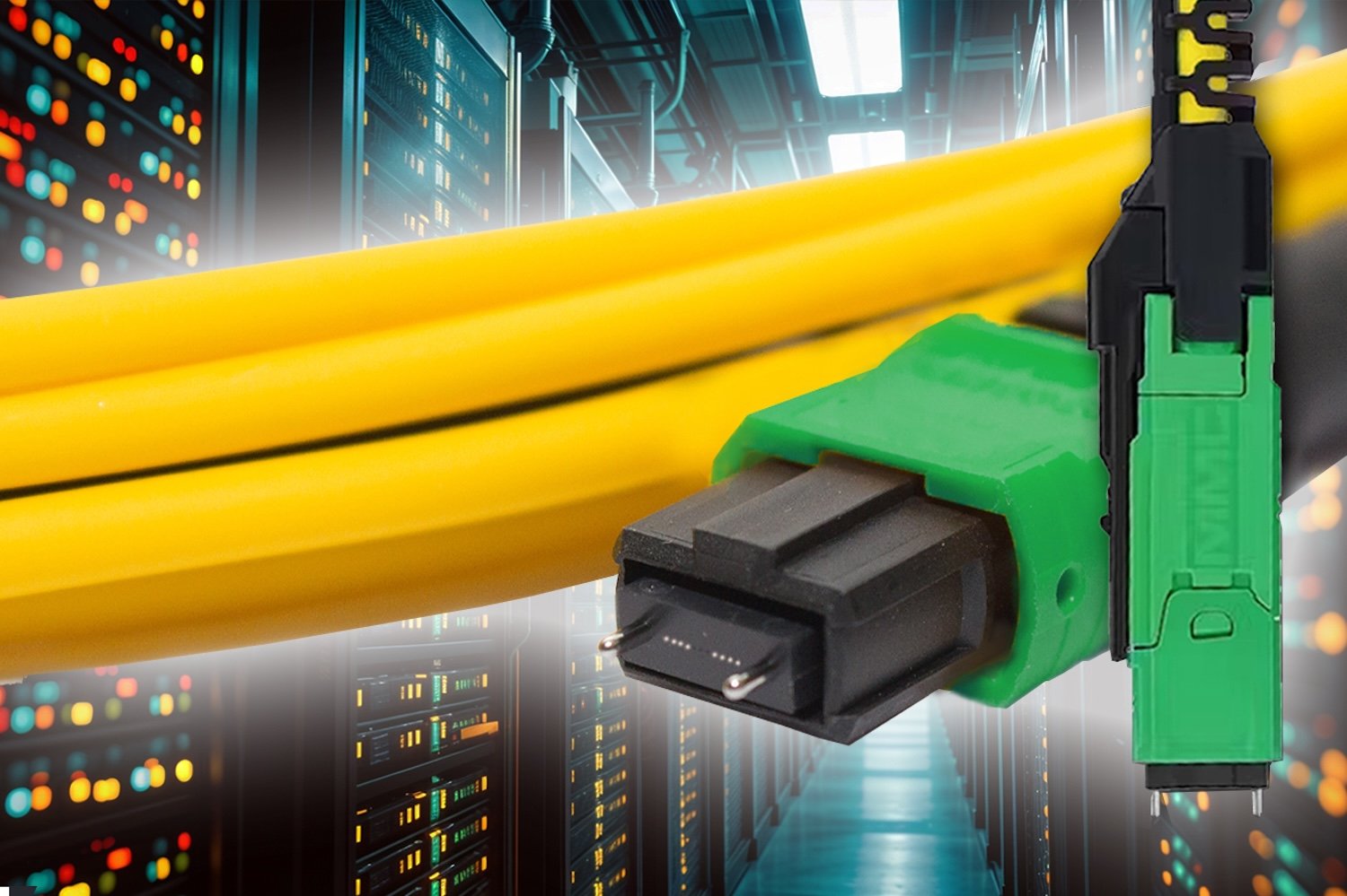
Multi-fiber push-on connectors (MPOs) are essential in data centers, especially as applications evolve to support faster speeds. The industry is adopting MPOs with higher fiber counts, new form factors, and angled end faces — all of which impact how they’re inspected, cleaned, and tested. These are the key considerations to keep in mind.
|
|
What Are the Different Types of MPOs?
MPOs come in multimode and single-mode versions with various fiber counts, including 8, 12, 16, 24, and 32. They come in pinned (male) and unpinned (female) versions; the unpinned versions connect to pinned equipment interfaces. To ensure correct alignment and polarity, MPOs are also keyed, though the key location varies between connectors.
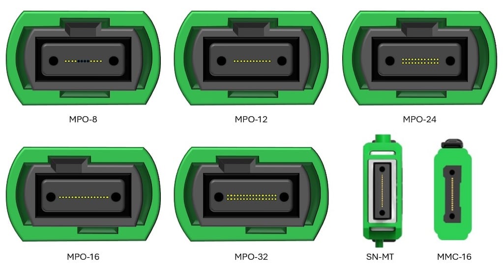
New very small form factor (VSFF) connectors are a type of MPO designed to save space in ultra-high-density environments. These include the SN-MT from Senko (available in 8- and 16-fiber versions) and the MMC from US Conec (available in 12-, 16-, and 24-fiber versions). Instead of a single horizontal row of fibers, these connectors use a vertical stacking approach to reduce housing width, offering three times the density of traditional MPOs.
|
Traditional MPOs are available in various fiber counts, with 8, 12, 16, 24, and 32 fibers being the most common for data center applications. VSFF SN-MT and MMC MPO connectors are designed to save space in ultra-high-density environments. |
Some MPO connectors are called MTP connectors, which is a trademark for US Conec’s MPO. The MTP is a fully compliant MPO engineered to tighter tolerances for better alignment, durability, and insertion loss. For instance, while the IEC specifies a maximum fiber height differential among all fibers of less than or equal to 0.0005 mm, US Conec specifies less than or equal to 0.0004 mm. Remember: All MTPs are MPOs, but not all MPOs are MTPs.
How Are MPOs Used?
Versatile MPO connectors serve three main purposes in the data center:
- • Consolidating backbone cabling
- • Supporting high-speed parallel optics
- • Facilitating breakout configurations
Backbone cabling
MPO trunk cables have been widely used to consolidate duplex backbone cabling in data centers for a long time. Instead of running numerous individual duplex cables between patching areas, MPO trunk cables connect to the rear of MPO-to-LC patch panel cassettes. The LC connections at the front of the cassette connect to equipment via duplex patch cords.
Consider that connecting two 48-port patch panels with duplex cables would require 48 individual cables (96 fibers). Using MPO-12 connectors at the rear of the patch panels reduces the number of cables to just eight, and using MPO-24 connectors reduces it to four. Fewer cables equate to faster installation, pathway space savings, and simpler cable management.
Parallel optics applications
MPOs are essential for parallel optics applications, which transmit and receive signals over multiple fibers to achieve faster speeds. These applications are defined by their lane speed and number of lanes. For example, an MPO-8 connector supports 100 Gig (4 fibers transmitting and 4 receiving at 25 Gbps), 200 Gig (4 fibers transmitting and 4 receiving at 50 Gbps), or 400 Gig (4 fibers transmitting and 4 receiving at 100 Gbps).
Newer 800 Gig applications require MPO-16 connectors (8 transmitting and 8 receiving at 100 Gbps). Advanced 200 Gbps per lane signaling will allow an MPO-8 connector to support 800 Gig and an MPO-16 connector to support 1.6 Terabit.
MPOs can support parallel optics and consolidate backbone cabling simultaneously. For example, using MPO-24 connectivity to transition to three MPO-8 connections is ideal for speeding installation and minimizing backbone cabling bulk in 8-fiber parallel optic applications.
Breakout configurations
MPOs facilitate breakout configurations where a single high-speed switch port connects to multiple lower-speed switches or servers. Breakout cables, which come in various forms, separate MPO fibers into multiple discrete connections. For example, a single 800 Gig (800GBASE-SR8) switch port can connect two 400 Gig servers (2X400GBASE-SR4), four 200 Gig servers (4X200GBASE-SR2), or eight 100 Gig servers (8X100GBASE-SR1).
It’s important to note that MPO trunk cables differ from MPO breakout cables.
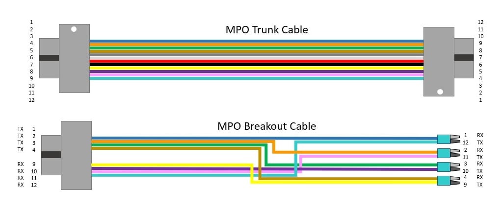
- • Trunk cables provide a direct, one-to-one fiber connection, with polarity achieved via cassettes and/or patch cords.
- • Breakout cables separate the fibers of the MPO into multiple discrete connections, as illustrated below.
|
MPO trunk cables provide a direct, one-to-one fiber connection. Breakout cables separate fibers into multiple discrete connections. |
The Rise of Multimode APC MPOs
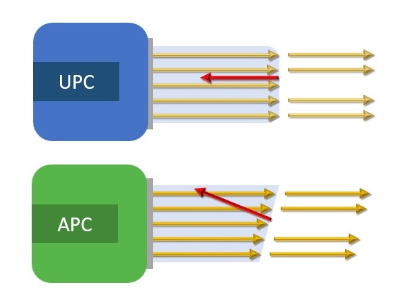
There are two types of fiber end faces: ultra physical contact (UPC) and angled physical contact (APC). UPC end faces are flat, while APC end faces feature an 8-degree angle that causes reflected light to be absorbed into the cladding, reducing reflections in the fiber core.
APC end faces were historically used for single-mode fiber in wavelength division multiplexing (WDM) applications, which operate at higher wavelengths and are more susceptible to reflections. APC single-mode connectors feature a green connector body to distinguish them from blue UPC single-mode connectors.
|
UPC fiber end faces are flat, while APC end faces feature an 8-degree angle to reduce reflections. |
All single-mode MPO connectors use APC end faces, because it’s virtually impossible to achieve good reflectance across multiple UPC fibers. That’s why you never see blue single-mode MPO connectors. APC single-mode MPOs are especially beneficial for short-reach single-mode 200GBASE-DR4, 400GBASE-DR4, and 800GBASE-DR8 data center applications that require superior reflectance performance.
It’s now more common to find APC multimode MPO connectors in data centers. While traditional 40 and 100 Gig parallel optic multimode applications worked well with UPC MPO connectors, high-speed PAM4 signaling in 400 and 800 Gig multimode applications is more sensitive to reflections. This has made APC multimode MPO connectors the new standard for these applications.
Inspection and Cleaning Considerations
Every connector end face should be inspected and cleaned, if necessary, before connecting — including factory-terminated MPO connectors fresh out of the bag. Proper inspection is especially critical for MPOs, since contaminants from one fiber can easily migrate to another within the same array.
Inspecting an MPO starts by inspecting the entire ferrule using a large field of view (LFOV) microscope. When inspecting, it’s critical to use the inspection tip that matches the MPO connector type and end face. Using a UPC tip to inspect an APC connector, or vice versa, prevents an adequate view of the entire end face for determining cleanliness. The Fluke Networks FI-3000 FiberInspector™ Ultra Camera comes standard with tips for inspecting both UPC and APC 8-, 12-, and 24-fiber MPO end faces. Accessory tips are also available for inspecting 16- and 32-fiber MPOs and VSFF MMC connectors.
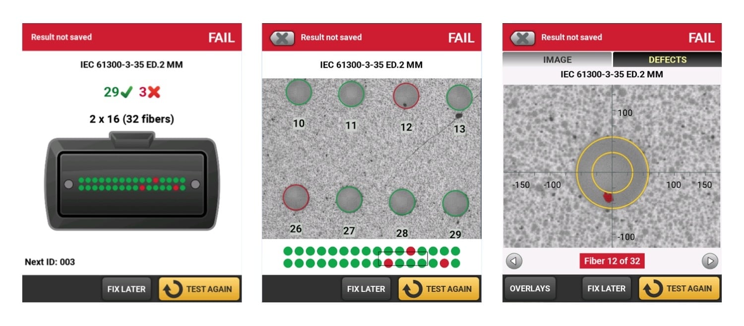
A key consideration for inspecting MPOs is the ability to view both the entire MPO array and individual fibers. Advanced inspection tools like the FI-3000 feature dual cameras to provide a single, integrated view, letting you zoom into a specific area, pan across the connector, or tap the image of a specific fiber for a detailed look.
The best inspection tools remove human subjectivity by automatically certifying connector cleanliness based on the number and size of defects in the critical zones of each fiber end face as defined in IEC 6300-3-35 standards. The FI-3000 uses algorithmic processes to quickly inspect, grade, and certify fiber end faces based on IEC standard criteria, providing automated PASS/FAIL results for each fiber of an MPO connector. The FI-3000 even offers PortBright™ illumination for inspecting MPOs in dark and crowded data center environments.
|
The Fluke Networks FiberInspector™ Ultra Camera allows users to switch seamlessly from a summary view (left) to an end face image (center), then use the gesture-based interface to zoom in on each fiber (right) and pan across the entire connector. Individual fibers are labeled so you know what you’re looking at. Red defects are failures; green defects are acceptable to the selected standard. |
If inspection shows loose particles on the end face surface of an MPO, the next step is to clean the connector. Use only solvents and cleaners specially formulated for fiber optics and MPOs, such as those in our Fiber Optic Cleaning Kits. Fluke Networks Quick Clean™ Cleaners are available for cleaning all types of MPO connectors, including VSFF MMC connectors.
How to Test MPOs
After any fiber installation, Tier 1 certification testing with an optical loss test set (OLTS) is essential to ensure links meet the length, loss budget, and polarity requirements of the design specification. It’s also required by most manufacturers to acquire a warranty on the fiber cabling system.
For parallel optic links that use MPO connectors, the best practice is to use a tester with an onboard MPO connector to match the link under test. Attempting to test these links with a duplex tester is time-consuming and prone to inconsistencies, because each fiber pair (send and receive) must be tested separately using fan-out cords or cassettes — all while keeping end faces clean during the process.
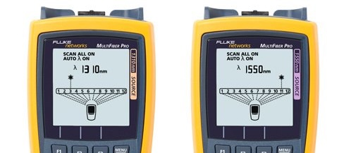
The Fluke Networks MultiFiber™ Pro MPO tester features an on-board MPO connector for testing parallel optic links. It can scan all fibers simultaneously at various wavelengths and display insertion loss results for the entire link. Fiber polarity is also more complex with MPO cables and connectors, so using a certification tester like the MultiFiber Pro, which can also test these links for correct polarity, is ideal.
|
The Fluke Networks MultiFiber™ Pro MPO tester scans all fibers simultaneously at various wavelengths and displays insertion loss results for the entire link. |
It's important to understand that not all fiber links that contain MPO connectors require an MPO tester. If you’re using MPO trunk cables to consolidate backbone cabling in duplex applications, you don’t need to worry about connecting the tester to the MPO. You are technically only testing the duplex link and will therefore connect your tester to the duplex port at the front of the patch panel where you will eventually connect your active equipment.
However, when testing these links, the loss results will include the loss of the duplex connectors at both ends, as well as the loss of the MPO connectors on either end of the trunk cable. While you don’t need to connect your tester to MPOs in this scenario, they should still be inspected (and cleaned if necessary) before connecting trunk cables.
The same holds for testing duplex breakout applications where a high-speed MPO port supports multiple lower-speed duplex ports, such as 4X100 Gig. You’re still technically testing four independent duplex links. However, an MPO-to-duplex fanout cable and the 3-jumper method may be required for testing these duplex links, depending on the configuration. The Fluke Technical Assistance Center (TAC) can provide guidance on testing various breakout configurations.
Keeping Pace with MPO Evolution
MPOs in the data center have evolved significantly, from their initial use in consolidating 10 Gig backbone cabling to supporting early 40 and 100 Gig parallel optics applications. As more data centers migrate to 400 and 800 Gig and even 1.6 Terabit speeds, and adopt cost-effective breakout configurations and VSFF versions, MPOs will remain crucial components of fiber optic links.
And Fluke Networks is evolving with them. We’re closely monitoring the evolution of MPO connectors in the data center and directing our R&D efforts to ensure that our fiber certification testers support the latest MPO applications and connector types.
Keep Learning
Recent Posts See All >
What Is PoE Negotiation?
2025-06-30
More General Posts See All >
MPOs in the Data Center and How to Test Them
2025-11-18


©2006-2021 Fluke Corporation。保留所有权利。
RM2011, 20/F, SCITECH Tower, 22 Jianguomenwai Avenue, Chaoyang District, Beijing, China
地址:北京市朝阳区建国门外大街22号赛特大厦20层2011室
联系电话:400-8103435
沪ICP备11037028号-15![]()