Why Wi-Fi Standards Keep Evolving
Wi-Fi has become the primary means of enterprise connectivity and continues to grow. Wireless devices demand greater bandwidth for streaming, video conferencing, augmented/virtual reality, and cloud computing. As a result, Wi-Fi standards have advanced to support ever-greater throughput with less interference.
Every Wi-Fi access point connects with cabling, which means there’s still a lot of wire in wireless. In the real world, contention, interference, and distance limitations limit Wi-Fi throughput to no more than 50% of theoretical maximums. Achieving that 50% and supporting future data rates requires the right cables connected to the access point.
Contents
- Ongoing Standards Development for Faster Wi-Fi
- The Next Generation: Wi-Fi 7
- Wi-Fi 5 Cabling Requirements
- Wi-Fi 6 Cabling Requirements
- Wi-Fi 7 Cabling Requirements
- Simpler Access Point Connections with MPTL
- PoE for Wi-Fi
- DC Resistance and Why You Should Test It
- Using Hybrid Copper-Fiber Cable to Power Wi-Fi Access Points
- Keep Learning
Ongoing Standards Development for Faster Wi-Fi
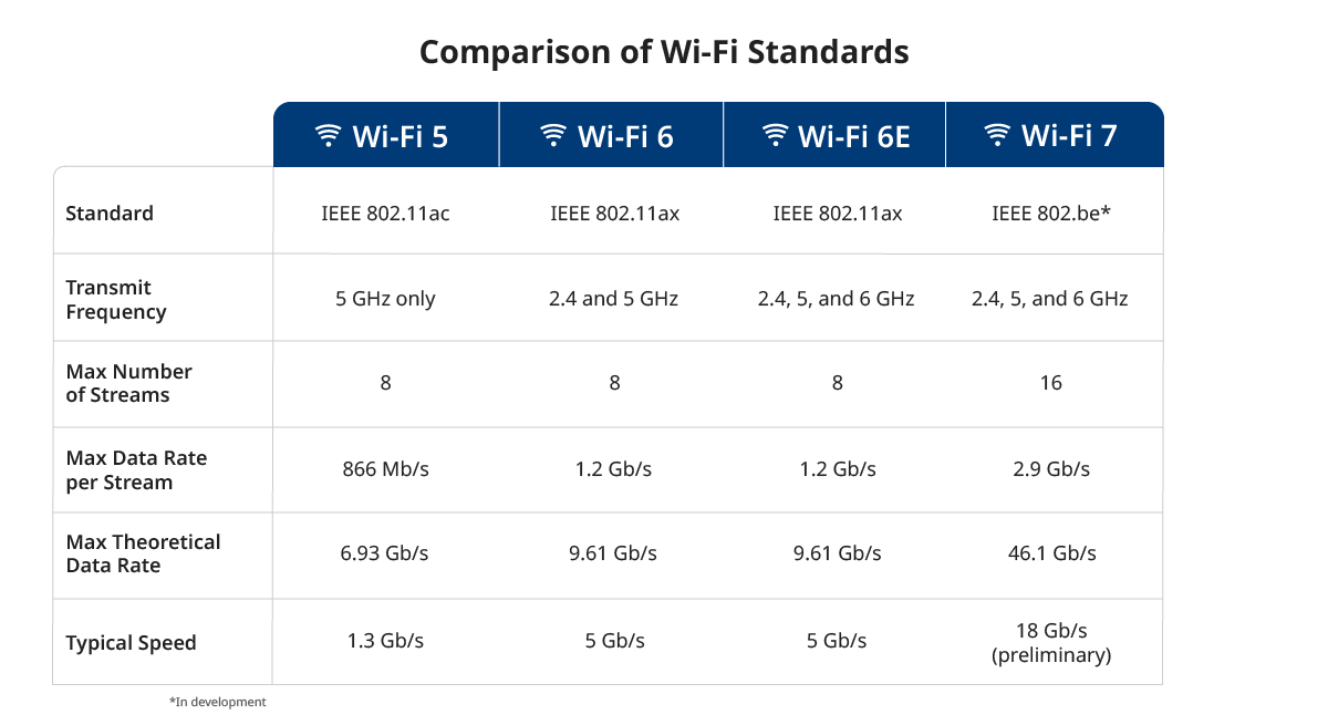
Most Wi-Fi deployments today meet the latest IEEE 802.11ax standard, Wi-Fi 6. It offers up to 4 times the speed of Wi-Fi 5 and has greater capacity to connect more devices.
While Wi-Fi 5 transmits only in the 5 GHz frequency band, Wi-Fi 6 transmits in both the 2.4 and 5 GHz bands with up to 8 spatial streams. The 2.4 GHz frequency band is more congested, with fewer channels and more interference. Its lower frequency, however, offers more range and better propagation to penetrate through building materials. This accommodates low-speed devices requiring greater reach for sending tiny amounts of data (like IoT/IIoT wireless sensors).
Wi-Fi 6 also leverages the less-congested 5 GHz band with more non-overlapping channels for higher-speed applications. In addition, Wi-Fi 6 offers reduced latency, better battery life, and greater power efficiency than Wi-Fi 5.
In April 2020, the FCC opened the 6 GHz frequency band to Wi-Fi use: Wi-Fi 6E. Still based on the 802.11ax standard, it adds channels for high-speed applications and/or high-density networks that serve many low-speed wireless devices. The 6 GHz band is also ideal for large arenas and stadiums.
Wi-Fi rollouts typically arrive in two waves. The differences between waves involves the number of special streams, antenna configurations, channel bandwidth, and additional features. For example, in Wi-Fi 5, Wave 1 devices had a top speed of 1.3 Gb/s. Wave 2 devices improved speed to 6.93 Gb/s by upgrading the antenna and using a wider channel. Wi-Fi 6 and next-generation Wi-Fi 7 are expected to roll out in two waves.
The Next Generation: Wi-Fi 7
The IEEE is already developing the next generation of Wi-Fi. Wi-Fi 7 (also called "extremely high throughput" or EHT wireless) is based on 802.11be standards and builds upon existing Wi-Fi 6 and 6E technology.
Wi-Fi 7 operates in the 2.4, 5, and 6 GHz frequency bands with up to 16 spatial streams. It also has greater channel bandwidth and size. It can simultaneously send and receive across the different bands while maintaining backward compatibility. Wi-Fi 7 has a maximum theoretical speed of 46 Gb/s and a preliminary expected throughput of at least 18 Gb/s.
Wi-Fi 5 Cable Requirements
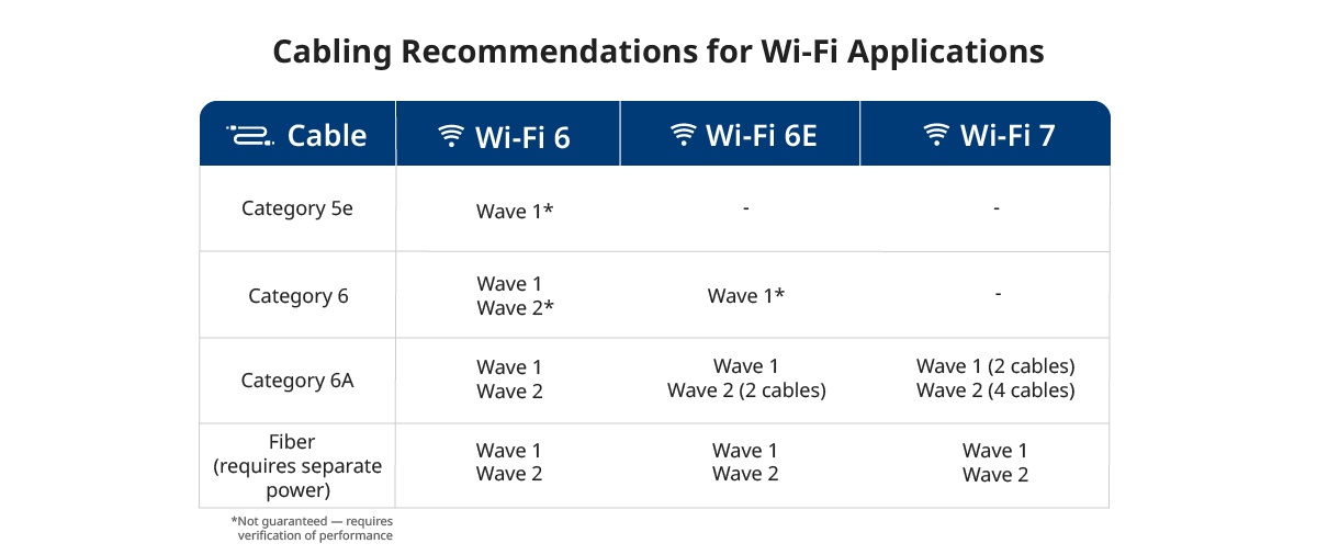
- • Wi-Fi 5 requires a Category 5e, 6, or 6A 2.5GBASE-T or 5GBASE-T connection, with 2.5GBASE-T supporting Wave 1 devices and 5GBASE-T supporting Wave 2 devices.
- • Not every installed Category 5e or 6 cabling plant is guaranteed to support 2.5/5GBASE-T due to alien crosstalk.
- • Existing Category 5e and 6 cabling plants should be evaluated for their ability to support 2.5/5GBASE-T.
Wi-Fi 6 Cable Requirements
- • Wave 1 Wi-Fi 6 access points should have at least one Category 6A (or Category 6 if the link is limited to 30 meters) 10 Gb/s connection (10GBASE-T). This gives a maximum data rate of 9.61 Gb/s and a typical data rate of 5 Gb/s.
- • For Wave 2 Wi-Fi 6, both TIA-568 and IEEE 802.11ax standards recommend two Category 6A connections for each access point to support full data rates. Most Wi-Fi 6 access points on the market today feature dual ports to accommodate the two connections.
Wi-Fi 7 Cable Requirements
- • Wi-Fi 7 access points require a minimum of two Category 6A 10GBASE-T connections.
- • Taking advantage of full Wi-Fi 7 data rates requires four connections. Installing the maximum number of cables at the start is more cost-effective than adding more later. Later additions can cost 10 times more than at initial deployment.
- • New Category 6A cable plants should plan for two cables to every Wi-Fi access point, at a minimum.
- • For maximum available throughput in Wi-Fi 7, deploy four Category 6A cables to every access point. Or connect the access points with a single multimode or single-mode fiber that can support 25 Gb/s and more.
Note that fiber cable can’t deliver power to the access point. It requires power via separate means. (More on that in Using Hybrid Copper-Fiber Cable to Power Wi-Fi Access Points below).
Simpler Access Point Connections with MPTL
A traditional wall plate and patch cord aren’t necessary for a Wi-Fi access point. Unlike a computer, for example, an access point doesn’t move. Eliminating outlets and equipment cords creates a neater, cleaner appearance and offers better security.
Recognizing this, TIA defined the Modular Plug Terminated Link (MPTL). This link starts in a patch panel and ends with a field-terminated RJ-45 plug, which connects directly to the access point. No patch panel or equipment cord is needed.
A variety of manufacturers have released field-terminated modular plugs to support this standard. If you’re familiar with installing RJ-45 patch cord-style plugs, these new designs are much easier to work with. Find out more about MPTLs.
Testing a link terminated to an RJ-45 plug with traditional channel adapters excludes the mated connection at the far end. Industry standards also created a new, more accurate MPTL test method using a patch cord adapter on one end. Learn how to test an MPTL.
PoE for Wi-Fi
Most wireless access points in commercial installations are powered via Power over Ethernet (PoE). This eliminates the need to install an AC outlet and mount a separate power supply. As Wi-Fi technology advances, its more complex processing requires higher levels of PoE.
For example, most Wi-Fi 5 devices operate primarily within Class 3 Type 1 PoE (13 W) or Class 4 Type 2 PoE (25.5W). But many Wi-Fi 6 access points require Class 6 Type 3 PoE (51 W). Wi-Fi 7 also requires Class 6 Type 3 PoE. Higher-end access points will likely need Class 8 Type 4 PoE (71.3 W).
To ensure that Wi-Fi access points have enough PoE power, you must confirm that the PoE class for the power sourcing equipment (in most cases, the switch) is compatible with the access point. Find out more about PoE classes, types, and standards: download our Guide to Successful Installation of PoE.
DC Resistance and Why You Should Test It
A more subtle power issue relates to the cabling. Supplying PoE over category cabling requires the DC resistance of the cabling to be low. Too much resistance and the power will dissipate before it reaches the access point.
The cable geometry must balance DC resistance between pairs and within a pair. If a pair is too far out of balance, the power will saturate the receiver’s transformers and interfere with data transmission.
Category cable is designed, manufactured, and tested to meet strict DC resistance requirements. But faulty installation techniques can add resistance to the link — and field-testing standards don’t require DC resistance measurements for certification.
The combination of high-speed 10GBASE-T, higher-power PoE, and more wireless devices make Wi-Fi 6 and Wi-Fi 7 the most significant modern technologies to substantiate the need for DC resistance testing.
- • You can find DC resistance testing on the Fluke Networks DSX CableAnalyzer™ Series tester by selecting (+All) or (+PoE) limits.
- • You can check how much power is available on a link in an installed cabling plant with a Fluke Networks LinkIQ Cable + Network Tester or MicroScanner™ Cable Verifier.
Find out more about PoE load testing and advanced troubleshooting.
Using Hybrid Copper-Fiber Cable to Power Wi-Fi Access Points
When you use fiber to connect Wi-Fi access points — which will become more common as Wi-Fi 7 is deployed — you need another way to provide power. The most cost-effective way to deliver that power is to use a hybrid copper-fiber cable that includes fiber strands for data and two copper conductors for power. The power delivered via hybrid copper-fiber cable is not PoE but is considered a Class 2 power-limited circuit according to the National Electric Code.
If the access point doesn’t have a fiber input, a hybrid copper-fiber cable can connect and power a PoE media converter, which in turn delivers PoE and data to the access point via copper category cable.
Hybrid copper-fiber cables don’t just provide the bandwidth and power needed to support high and extra-high throughput Wi-Fi. They also allow for extending distances beyond the 100-meter limitation of category copper cabling — which makes Wi-Fi feasible in locations like warehouses, parking garages, and outdoor spaces. Learn more about using hybrid copper-fiber cable to power Wi-Fi.
Keep Learning
- • So You Want to Upgrade to Wi-Fi 6?
- • Make Sure Your Cabling Plant is Ready for Wi-Fi 6
- • What Is the Right Way to Test an MPTL?
- • How to Test if Your Ethernet Cables Support PoE
- • DC Resistance Unbalance between pairs - DSX CableAnalyzer
- • White Paper: A Guide to Successful Installation of Power over Ethernet
Related Products
DSX CableAnalyzer™ Series Copper Cable Certifiers

LinkIQ™ Cable+Wi-Fi+Network Tester
CertiFiber® Pro Optical Loss Test Set
MicroScanner™ Cable Verifier Series


