OTDR: Your Ultimate Troubleshooter
August 11, 2025 / General, Upgrading and troubleshooting
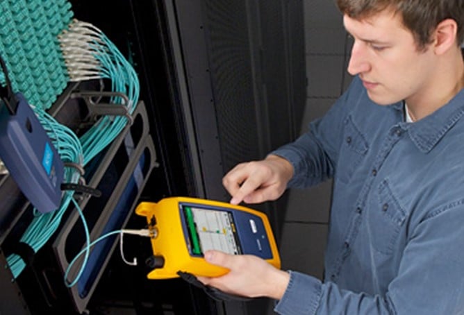
You're ready to use an optical loss test set (OLTS) for Tier 1 fiber certification. If some critical fiber links exceed the application’s loss budget, however, you’ll need to troubleshoot. An OLTS ensures the most accurate insertion loss measurement, but it can't pinpoint the exact location of the loss. Now an optical time domain reflectometer (OTDR) becomes your ultimate troubleshooting solution.
How an OTDR Helps You Find Fiber Problems
An OTDR works by transmitting high-power light pulses into the fiber and measuring the light reflected from any event or the end of the fiber due to a change in the refractive index. A small portion of the pulse light is also scattered due to impurities in the fiber, known as backscatter. The OTDR calculates the reflectance of an event by comparing output power to the reflected light, excluding backscatter.
Problems with fiber links often stem from damage somewhere along the fiber or from poor connections. An OTDR can characterize the entire link, identifying the precise location of any events that reflect or reduce light signals — including connectors, splices, microbends, kinks, cracks, or sharp bends. Access to this level of detail gives you a complete picture of the fiber installation and the overall quality of the workmanship. OTDR testing is required for Tier 2 certification.
Understanding Fiber Optic Reflectance
Reflectance is measured in dB as a negative value, with values closer to 0 indicating greater reflectance. (Note that reflectance is the same as return loss, which is expressed as a positive value comparing input power to output power.) While all connections in a fiber link create some reflectance, excessively high reflectance values indicate a problem, potentially leading to insertion loss failures that prevent the link from passing Tier 1 certification testing.
Here are some typical reflectance values for comparison:
- • Good multimode UPC (ultra physical contact) connection: -35 dB or lower
- • Good single-mode UPC connection: -50 dB or lower
- • Good APC (angled physical contact) connection: -60 dB or lower
- • Good fusion splice: -60 dB or lower
High reflectance can result from contaminated, damaged, or improperly polished fiber end faces, poorly terminated connectors, or faulty fusion splices that create air gaps and core misalignments. Cracks, breaks, open fiber ends, plus microbends and macrobends (due to installation stresses like exceeding bend radius or pulling tension requirements) also cause reflectance. Mismatched fiber types, with their varying construction and core sizes, can be culprits as well.
Why Reflectance Matters More for Single-Mode
While multimode transceivers are highly tolerant of reflection, higher-power single-mode transceivers are not. Excessive reflection can even destroy a single-mode transceiver. This is why single-mode systems primarily use APC connectors, which offer superior reflectance. An APC connector’s end face is slanted at 8 degrees, preventing reflected light from going straight back toward the source.
Reflectance is increasingly crucial for emerging short-reach single-mode applications in data centers, such as 100GBASE-DR, 200GBASE-DR4, and 400GBASE-DR4. Although these applications utilize lower-power lasers for 500-meter or 2000-meter single-mode links (which are more cost-effective than long-haul single-mode applications using high-power lasers), they have more stringent insertion loss requirements that depend on reflectance.
For short-reach single-mode applications, IEEE specifies insertion loss limits based on the number and reflectance of connections. Having more connectors with higher reflectance values requires a lower maximum insertion loss. When you’re troubleshooting the fiber links supporting these applications, an OTDR helps determine the reflectance and number of connections needed to verify the maximum insertion loss.
Best Practices for OTDR Troubleshooting
Remember these best practices for troubleshooting with an OTDR:
- • Test at both 850nm and 1300nm wavelengths for multimode, and at 1310nm and 1550nm for single-mode. Even if the application only uses the lower wavelength for transmission, testing at the higher wavelength can reveal problems more easily. Normally, the higher wavelength would show lower loss, but if the fiber is stressed, it will exhibit significantly higher loss.
- • Troubleshoot in both directions. A mismatched splice might appear as a gainer (negative loss) in one direction and show too much loss (false loss) in the other direction. Bidirectional testing (required for Tier 2 testing) averages the loss from both directions to determine the actual loss of the connection. The Fluke Networks OptiFiber® Pro OTDR simplifies bidirectional testing with its built-in SmartLoop™ Assistant. By using a launch cord to connect the fibers together at the far end of the link, SmartLoop automates bidirectional testing without needing to move the OTDR to the far end of the link. The bidirectional averaging is done directly on the tester, eliminating the need for additional software or manual calculations to determine the actual loss of a connection.
- • After troubleshooting with an OTDR, you still need an OLTS to precisely measure total insertion loss and ensure application compliance. While an OTDR can infer the total loss of a fiber link by calculating the difference between the amount of reflection at the near and far ends, this calculation may not accurately represent the total loss once the link is live. Especially in the case of multimode fibers, where standards specify precisely controlled launch conditions, OTDR insertion loss results are not as accurate or repeatable as those obtained with an OLTS.
Why the OTDR Trace Is Important
When you troubleshoot with an OTDR, you get a graphical signature of a fiber's loss along its length. While an OTDR trace can seem a bit overwhelming, it tells a complete story about the fiber link, with each dip or spike revealing the type of event.
Experienced OTDR trace readers can identify reflective trace events for tester connectors, launch cords, connectors, mechanical splices, fusion splices, mismatched fibers, and the end of the link. They also know that the little blips after the end of the link are ghosts, which are not real events of concern.
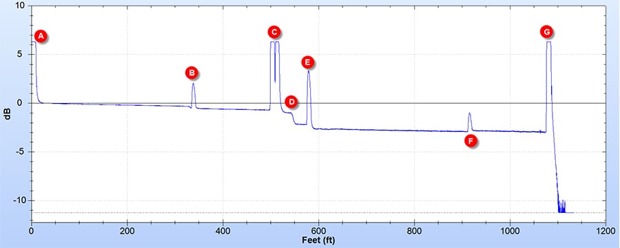
The typical OTDR trace below illustrates length and a gradual decline in light strength with various reflective events:
- • Event A represents the OTDR’s connector. Its large reflectance makes it impossible to characterize the loss in the first connector of the link under test. However, in this case, a launch fiber of about 300 ft. is used to allow the OTDR to characterize Event B, the first connector of the link under test.
- • Event C illustrates two connectors situated too close together for the OTDR to individually characterize their losses.
- • Event D is a loss event with no reflectance, likely caused by a bad splice or APC connector. In contrast, Event E shows a typical UPC connector exhibiting both reflectance and loss.
- • Event F depicts a connector with reflectance, where the signal after the connector is stronger than before, known as a "gainer." This is indicative of connecting fiber types with different backscatter properties.
- • Event G is the end of the fiber. The strong reflection here makes it impossible to determine if a connector is present or to assess its performance.
|
Typical OTDR trace showing various reflective and non-reflective events. |
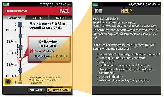
Don’t worry if you’re not a trace analysis expert. The OptiFiber® Pro utilizes advanced logic to interpret the trace and provide an EventMap that characterizes events. Faulty events are highlighted with red icons so you can quickly pinpoint problems. For even more help, the help icon on the bottom left of the EventMap screen suggests corrective actions. Now that definitely makes for the ultimate troubleshooting tool!
|
EventMap view with on-screen help |
Recent Posts See All >
What Is PoE Negotiation?
2025-06-30
More General Posts See All >
MPOs in the Data Center and How to Test Them
2025-11-18
Explore Our Products
OptiFiber® Pro OTDR Family


©2006-2021 Fluke Corporation。保留所有权利。
RM2011, 20/F, SCITECH Tower, 22 Jianguomenwai Avenue, Chaoyang District, Beijing, China
地址:北京市朝阳区建国门外大街22号赛特大厦20层2011室
联系电话:400-8103435
沪ICP备11037028号-15![]()