The Skinny on 28 AWG Patch Cords
June 27, 2018 / General, 101 learning, Installation and testing, Industrial Networks
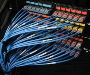
Over the past few years, several manufacturers have released 28 AWG patch cords that offer a smaller diameter to help improve airflow around active equipment and ease cable management at high density patching areas due to reduced congestion and a smaller bend radius.
Despite causing a bit of controversy in the industry since they were not originally recognized within ANSI/TIA cabling standards that require twisted-pair structured cabling to consist of 22 AWG to 26 AWG cables, these skinny patch cords continued to grow in popularity.
But the controversy is over. A couple of weeks ago, the TIA Engineering Committee TR-42 voted to approve the new ANSI/TIA-568.2-D cabling standard which now allows for the use of 28 AWG patch cords, and ISO/IEC will likely follow suit. So we thought it was a good time to give you skinny on the skinny.
Matters of Resistance
The DC resistance of a conductor is essentially a measure of the conductor’s ability to resist the flow of electric current, and it increases with the length of conductor. It is also relative to the size of the conductor—larger gauge sizes exhibit less DC resistance than smaller gauge sizes. So Skinny 28 AWG patch cords inherently have more resistance.
In testing twisted-pair cabling, we look at DC loop resistance. This is the total resistance through two conductors in a pair looped at one end. DC resistance is impacted by both the conductor diameter and the overall length—not only do smaller conductors exhibit more DC resistance, but it also increases proportionately with the length of the cable. According to IEEE standards, the channel DC loop resistance of a pair shall be 25 Ohms (Ω) or less while permanent link DC loop resistance shall be 21 Ω or less.
What does this mean for skinny patch cords? To stay within the DC loop resistance channel limit of 25 Ω, the new TIA 568.2-D standard recommends keeping the length of 28 AWG patch cords in a channel to less than 15 meters.
While not typically a concern in switch-to-server links in the data center environment, when 28 AWG patch cords are used in remote powering applications (either today or in the future), they are subject to greater heat rise than larger patch cords so avoiding large bundles should be a consideration in these instances. In fact, both TIA and ISO/IEC have active projects to update remote powering guidance to consider 28 AWG cables.
If you do exceed the DC loop resistance, be sure to look at all the pairs on your DSX CableAnalyzer™ Series copper cable certification tester. If just one pair has failed, it is likely a poor termination rather than the use of a skinny patch cord. But if all pairs fail in a channel using 28 AWG cords, you may have gone too far.
More Loss to Derate
From a signal perspective, insertion loss is considered an even more important performance parameter. The loss of signal is a natural phenomenon that occurs for any type of transmission along the length of any cable, and just like DC resistance, it is impacted by both the conductor size and overall length. So in addition to higher DC resistance, 28 AWG patch cords also exhibit higher insertion loss
Since loss is directly related to the length of a channel, the use of 28 AWG patch cords requires the overall length of the channel to be reduced. Reducing channel length to less than 100 meters (comprised of 90 meters of permanent link cabling and 10 meters of patch cords) is referred to as derating, and different types of cables and applications include a de-rating factor to accommodate for insertion loss. For example, since heat causes insertion loss, cables have a derating factor at higher ambient temperatures.
Due to increased insertion loss, the derating factor for 28 AWG patch cords is recommended to be 1.95, which reduces the overall length of a 100-meter channel to 96 meters—90 meters of permanent link cabling and 6 meters of patch cords. If there is a need to maintain 10 meters of patch cords, the channel length will need to be reduced even further. For example, using a derating factor of 1.95 and the calculation for the maximum length of a channel, which must be less than 102 meters, the total permanent link length when using 10 meters of 28 AWG patch cords is 82.5 meters (i.e., 92.5-meter channel).
102 meters - (1.95 derating factor X 10 meters) = 82.5 meters
Using this same calculation, only about a 73-meter permanent link is supported if you use the maximum recommended length of 15 meters for your 28 AWG cords (i.e., 88-meter channel). So if your channel includes 28 AWG patch cords that are longer than a total of 6 meters, and you fail insertion loss testing, there’s a good chance that your permanent link length will need to be reduced from its normal 90 meters.
However, there isn’t a lot of concern about derating among most users since these skinny cords are deployed primarily in high-density patching areas in data centers where link lengths tend to be well below 90 meters anyway. Overall, the consensus in the industry is that the pros of 28 AWG patch cords (improved airflow and cable management) significantly outweighs the cons (reduced channel length). And that’s precisely why these skinny cords are now recognized by industry standards.
Recent Posts See All >
What Is PoE Negotiation?
2025-06-30
More General Posts See All >
MPOs in the Data Center and How to Test Them
2025-11-18
Explore Our Products
DSX CableAnalyzer™ Series Copper Cable Certifiers


©2006-2021 Fluke Corporation。保留所有权利。
RM2011, 20/F, SCITECH Tower, 22 Jianguomenwai Avenue, Chaoyang District, Beijing, China
地址:北京市朝阳区建国门外大街22号赛特大厦20层2011室
联系电话:400-8103435
沪ICP备11037028号-15![]()