Extending and Testing Cable Runs Beyond 100 meters
October 8, 2020 / General, 101 learning, Installation and testing, Best Practices
In our last article on how to connect end devices beyond copper Ethernet’s 100 meter range, we looked at various solutions to the dilemma of needing to connect an end device that’s just a little too far from the nearest telecommunications room (TR), including building a new TR, the use of an extender device, fiber or extended-distance cabling.
While the use of extended-distance cabling is technically a non-standard-compliant approach, it is the cheapest and easiest option, which has it gaining in popularity. That’s why many vendors have introduced new cable designs and/or are providing performance information for existing cables in beyond 100m deployments.
Since you might be asking just how these cables are able to go the distance, we thought it might make sense to take a closer look at why we have the 100m limitation for twisted-pair copper cabling in the first place, how cables can go the distance and how best to handle testing.
It’s All Physics
The 100m distance limitation for a 4-connector channel that includes a 90m permanent link and 5m of patch cable at both ends is based primarily on worst-case performance factors for a given application. Industry standards organizations figured out three decades ago when developing the first twisted-pair cabling standards that at the maximum frequency for a given application and length, certain performance parameters impacted the ability of the signal to properly reach (or be interpreted by) the far end. Insertion loss (i.e., signal attenuation) for example is a primary limiting factor. This reduction of signal happens along any length of cable for any type of transmission—and the longer the length, the greater the loss.
Based on these performance parameters, industry standards standardized on the 100-m distance and have stuck with it even as new applications with higher frequencies and new cable constructions were introduced. It has significantly simplified the development of performance specifications. Think about it. If you always stick with 100 m, the performance parameters can easily be extrapolated for each generation of cabling based on frequency of the application that it’s intended to support. That’s why category 5e has an insertion loss maximum of 24 dB while category 6 is at 21.3 (the lower the dB for insertion loss, the better). It’s important to note that there are other factors that can influence insertion loss such as resistance and heat. That’s why smaller-gauge wires with more resistance or deployments where the ambient temperature is above 20°C (68°F) can require length de-rating.
Another performance parameter related to length is propagation delay—the amount of time it takes for a transmitted signal to be received at the far end. In twisted-pair cabling, delay is related to the nominal velocity of propagation (NVP), as well as the length of the cable and the operating frequency. NVP characterizes how fast a signal travels down the cable relative to the speed of light in a vacuum and there is a maximum that can be supported without loss of signal. Due to various pair twists, the delay can be different across pairs, which is a problem when multiple pairs are carrying data. The difference between the pair with the least delay and the pair with the greatest delay (calculated as propagation delay skew) must be low enough for network equipment to properly interpret the signal, and longer lengths can exasperate the difference.
So, What Does it Take?
Now you know that the 100m distance limitation relates to several factors—frequency, insertion loss, resistance, temperature and propagation (all mixed in with a little history). So, if that’s the limit, how can cable vendors offer extended-length cable?
Transmission speed has a lot to do with extended-length cables. Since standards are based on worst-case scenario and minimally compliant components, most reputable cabling and connectivity vendors already offer headroom by exceeding the standards. Many devices that need to extend beyond the 100m distance are also lower-speed devices such as access control devices (think parking lot entrance gates), emergency call boxes (like you see on college campuses), and security cameras (like the one at the far corner of the warehouse). One way to support extended lengths is to use a cable capable of supporting a much higher bandwidth than the device requires. For example, Anixter Utility Grade UTG20 cables can support 10 Mbps transmission to 185 meters, 100 Mbps to 150 meters, 1 Gbps to at least 100 meters and 10 Gbps to 100 meters.
There are also characteristics of cable that impact length, such as conductor size, shielding, pair twist and even the dielectric material that form any insulation and cable jacket. Since larger gauge wires have less resistance and therefore better insertion loss, some extended-length cables feature 22 or 23 AWG conductors rather than 24 AWG. Paige GameChanger UTP extended-distance cable is 22 AWG.
DC resistance unbalance also comes into play—if the difference in DC resistance between two conductors is too high, common mode voltage such as PoE is not equally split, which can further distort data signals. So many extended-length cables are also carefully manufactured to ensure good DC resistance unbalance performance. Remember that heat can also impact insertion loss. Since shielded cables can better dissipate heat associated with temperature build-up from PoE and surrounding ambient temperature, some extended-length cables are also shielded. Fully-shielded cables may be able to support even greater distances.
Testing Vendor Specific Links
If you choose to deploy an extended-reach cable, first understand that the installation will not be standards compliant. That might be just fine with your customer, but it’s best to make sure. You may just need to educate them about the solution. And just because something isn’t standards compliant, doesn’t mean you don’t have to test it. If anything, testing is even more important when attempting to get a little extra performance out of the cabling—even if the cable is verified and approved by a vendor for longer-distance runs. If you don’t test to their spec and it ultimately doesn’t work, you’re liable and on the hook for the rework.
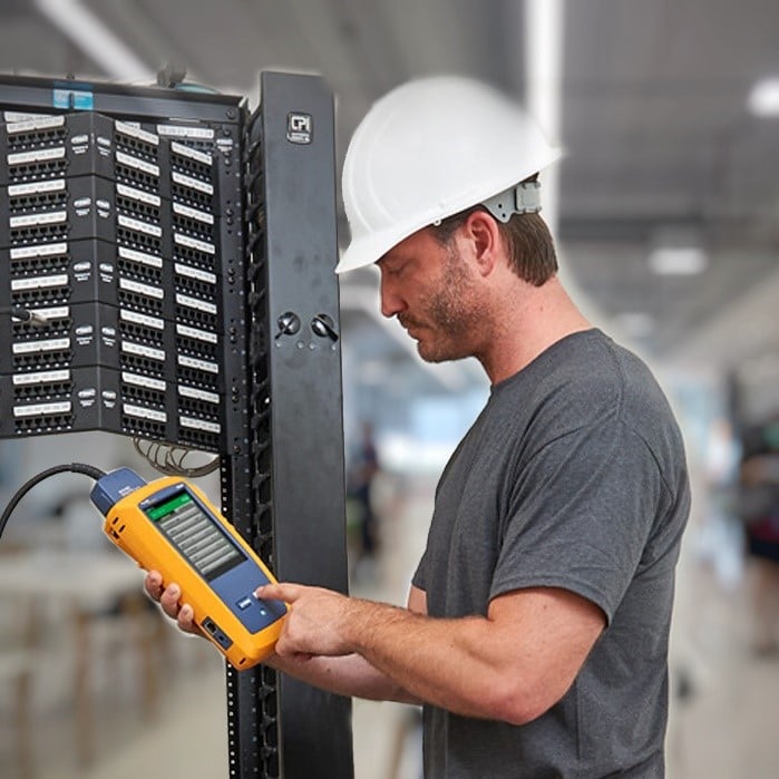
Thankfully, Fluke’s modular Versiv firmware makes it simple for us to add vendor-specific limits to our DSX CableAnalyzer series of copper cable certifiers for easy pass/fail testing of extended-reach cable. In fact, we’ve already done this for both UTG-rated, Paige GameChanger and Belden Long Reach cables—all you need to do is select these test limits on your tester.
Because it’s the cheapest and easiest option for connecting an end device too far from the TR, more vendors will likely start offering extended-reach cable or approving existing cables for distances beyond 100 meters. While some vendors are working with custom limits for specific jobs, we don’t recommend that you try this on your own as it introduces the potential for human error and prevents you from acquiring an easy pass/fail indication on your tester. Plus, it’s important to understand what is affected when you change one limit—you can’t just change one without affecting others.
The best option is for Fluke to work with your cabling vendors to also add their specific extended-distance limits to our DSX tester for easy pass/fail testing. Reach out to us for more information, or have your vendor contact us.
Recent Posts See All >
What Is PoE Negotiation?
2025-06-30
More General Posts See All >
MPOs in the Data Center and How to Test Them
2025-11-18
Explore Our Products
DSX CableAnalyzer™ Series Copper Cable Certifiers


