WHITE PAPER
Standard Compliant Certification & Best Practices
Download PDF
Overview
Despite industry best practice of inspecting and cleaning fiber optic endfaces, contaminated connections remain the number one cause of fiber related problems and test failures in data centers, campus and other enterprise or telecom networking environments.
On This Page
- Standard Compliant Certification & Best Practices
- Cleaning for Performance
- Inspecting for Assurance
- Grading and Certification via Standards
- Knowing What to Inspect and Clean
- Understanding Tools and Consumables
- Summary
- FI-7000 FiberInspector Pro Automatically Certifies Fiber EndFaces to IEC Standards
- Fluke Networks Fiber Test Solutions
Standard Compliant Certification & Best Practices
As the industry moves to higher data speeds, more stringent loss budgets and new multifiber connectors, proactively inspecting and cleaning fiber endfaces is more important than ever to ensure network uptime, performance and equipment reliability.
Even when users think they have properly cleaned the fiber, every connector endface either field terminated or factor terminated should always be inspected before connecting to a component or piece of equipment. However, relying on subjective human inspection of fiber endfaces often produces inconsistent results.
Thankfully, International Electrotechnical Commission (IEC) industry standards and new innovations enable automatic, consistent and repeatable certification of fiber cleanliness based on specific acceptance criteria.
Cleaning for Performance
Every fiber installation relies on proper endface cleaning practices for good reason. Network performance is only as good as the weakest link, and the weakest link is wherever a fiber endface is exposed – whether at a patch panel, equipment port or at the end of a patch cord or jumper.
Regardless of the type of fiber, application or data rate, the transmission of light requires a clear pathway along a link, including through any passive connections or splices along the way. A single particle on the core of a fiber can cause loss and reflections, resulting in high error rates and degraded network performance. Contamination on a fiber endface as shown in Figure 1 can also adversely impact the interface of expensive optical equipment, and in some cases even render equipment inoperative.
With fiber networks at the core of a business’s most important asset – the data center – and with the need to keep up with consumer demand for high-speed access to information anywhere and anytime, downtime and poor network performance are simply no longer an option. As network applications require more bandwidth and transmission speeds continue to climb from 1 and 10 gigabits per second (Gbps) to 40 and 100 Gbps, loss budgets have become tighter than ever. Dirt, dust and other contaminants are the enemies of these higher-speed data transmission rates over fiber networks. It is therefore critical that all optical connections be kept free of contamination to avoid application performance issues.
With contamination being the single greatest cause of fiber failures, spending the extra few seconds to properly inspect and clean every connector endface will save time and money in the long run.
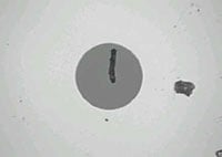
Figure 1: Dirty fiber endfaces as shown here can degrade network performance or damage equipment
While accidently touching a fiber endface and working in dirty, dusty construction environments are known causes of contamination, there are plenty of other ways to mishandle fiber that may not be obvious sources of contamination. Brushing an endface on clothing that can contain body oils, lint or other substances can cause contamination. In fact, any time an endface is exposed to the surrounding environment, it is subject to contamination – even if it was recently cleaned. Dust in the air can easily collect on a fiber endface, especially in the presence of static electricity.
Contamination also easily migrates from one port to another every time a connector endface is mated. Even a dust cover designed to protect the fiber endface can be a significant source of contamination. Unfortunately, many users are under the impression that if the endface was previously protected by a dust cover, it must be clean. However, no one can really know for sure what was in that dust cover. This is even the case for endfaces on new factory-terminated connectors. While dust caps are great at preventing damage to the endface, the plastic used to create dust caps can emit a residue as it deteriorates over time and the surface of the cap may contain mold-release substances used in high-speed production processes. Therefore you should not be surprised to find a contaminated endface upon removal of a protective cap on a connector fresh out of the bag.
Many also believe that an endface plugged into a piece of equipment must be clean and can therefore be unplugged and remated without concern. However, this too can cause contaminants to pass from one endface to another. Even if the initial contamination was outside of the fiber core, mating can break up a contaminant and cause particles to travel across the endface and redeposit on the core. The same holds true for equipment ports, which are often overlooked as being a source of contamination.
Inspecting for Assurance
It is not enough to just clean every fiber endface. Users have no way of knowing if the endface is clean unless they inspect it using a fiber inspection tool designed specifically for that purpose, such as a professional video microscope or a handheld fiber microscope. That is why the golden rule is to always inspect, clean and inspect again before connecting.
In fact, the very act of cleaning the endface can cause contamination. Every endface should be inspected after every cleaning attempt.
This is especially a concern for multi-fiber connectors such as the multi-fiber push-on (MPO) style connectors that are rapidly becoming the norm in today’s data center fiber backbone channels as the required interface for 40 and 100 gigabit Ethernet (GbE) applications (see Figure 2).
Consider a 12-fiber MPO interface with an array that features a much larger surface area than a single fiber connector. When cleaning these larger surface areas, it is much easier to move contaminants from one fiber to another within the same array. And the larger the array, the higher the risk. With 24-, 48- and 72-fiber MPOs used in high-density fiber interconnects, the greater number of fibers are more difficult to control and not all the fibers always protrude at the same height. Height variances across the fibers in a single multifiber connector can increase the risk of not every fiber being properly and equally cleaned.
Grading and Certification via Standards
One of industry’s longtime concerns with manually inspecting fiber endfaces for cleanliness has been that determining cleanliness has largely been a subjective and inconsistent process. What one person deems as clean can vary greatly from another person’s point of view. Additional variables such as skill level, years of experience, eyesight, ambient lighting and the fiber inspection tool being used can also lead to inconsistencies in determining fiber endface cleanliness. With more fiber networks being installed and maintained by a greater number of individuals, there is also a greater chance of inexperience regarding what constitutes endface cleanliness.
In an effort to establish consistency in fiber inspection and achieve more repeatable results for performance across multiple endfaces, the IEC developed 61300-3-35 Basic Test and Measurement Procedures Standard for Fiber Optic Interconnecting Devices and Passive Components. This standard contains specific cleanliness grading criteria to assess pass or fail certification for inspection of a fiber endface, removing the human subjectivity factor.
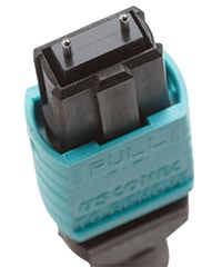
Figure 2: MPO connectors required for 40 and 100 GbE applications should always be inspected as it can be difficult to ensure that all fibers in the array were properly cleaned.
The certification criteria in IEC 61300-3-35 varies based on connector type and fiber size, as well as types of defect. Defects include pits, chips, scratches, cracks, particles and embedded and loose debris, and the IEC standard categorizes them into two groups - scratches and defects. Scratches are identified as permanent liner surface features while defects include all detectable non-linear features that can typically be cleaned. Certification to determine pass or fail is based on the number of scratches and defects found in each measurement region of the fiber endface, including the core, cladding, adhesive layer and contact zones, as well as the quantity and size of the scratches and defects (see Figure 3).
For example, as shown in Table 1, multimode fiber with polished connectors can have no scratches greater than 3 μm in width or defects greater than 5 μm in width. Within the cladding zone, there can be no scratches or defects greater than 5 μm in width, 5 defects ranging between 2 and 5 μm in width and no limit on the number of defects less than 2 μm in width. The number and size of scratches and defects allowed in each zone varies based on the connector type and diameter.
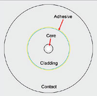
Figure 3: IEC 61300-3-35 grades fiber cleanliness based on the quality and size of scratches and defects in each region of the endface.
| Zone | IEC 61300-3-35 Recommended Acceptance Criteria Multimode Polished Connectors | |
|---|---|---|
| Scratches (maximum number of a given dimension) | Defects (maximum number of a given dimension) | |
| Core |
No limit ≤ 3 μm None > 3 μm |
4 ≤ 5 μm None > 5 μmm |
|
Cladding 65 μm to 11 μm |
No limit ≤ 5 μm None > 5 μm |
No limit > 2 μm 5 from 5 μm to 10 μm None > 10 μm |
|
Adhesive 115 μm to 135 μm |
No limit | No limit |
|
Contact 135 μm to 250 μm |
No limit |
None < 20 μm 50 from 20 μm to 30 μm None > 30 μm |
While the IEC 61300-3-35 standard can be used as a guideline for manually grading cleanliness, a manual procedure would require technicians to determine the size and location of the scratches and defects, which can still introduce human error and inconsistency.
Thankfully automated certification solutions like Fluke Networks’ FI-7000 FiberInspector Pro use algorithmic processes to automatically and quickly inspect, grade and certify fiber endfaces based on the criteria of the IEC standard.
These types of devices eliminate human subjectivity and result in faster, more accurate and repeatable results to help ensure optimum fiber network performance (see the FI-7000, below).
Knowing What to Inspect and Clean
The best answer to the question of what to inspect and clean is everything – every endface should be inspected, and every endface that fails IEC 61300-3-35 certification should be cleaned (see Figure 4). If upon inspection, the endface passes IEC certification, do not clean it. Cleaning can attract dust due to static electricity.
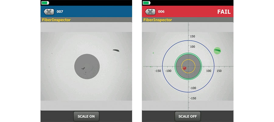
Figure 4: Is the endface shown on the left clean or dirty? Automated certification demonstrates that it is dirty per IEC 61300-3-35 due to defects in the core.
Any and all endfaces, even brand new ones and factory-terminated plugs and pigtails, should be inspected for cleanliness before mating. That includes both ends of fiber optic test cords, fiber jumpers and pre-terminated trunk cables.
If using an adapter to mate two plugs, the endfaces on both sides and the sleeve of the adapter itself should be inspected and cleaned before inserting them into the adapter. Interchangeable adapters used with optical power meters also need to be inspected and cleaned on a regular basis. Often the adapter has a light shield with pin hole that can accumulate debris. Always consult the documentation that came with the testing equipment as some vendors require sending certain adapters back for factory cleaning.
When testing or troubleshooting any equipment, including the tester itself, all plugs and ports should be inspected and cleaned before mating. That includes test equipment ports, adapters, test cord endfaces and any ports into which you will be connecting the test cord.
As previously mentioned, dust caps and mating can be a source of contamination. Therefore every time a fiber endface is unplugged or removed from a dust cap or port, even when it is brand new, it should inspected and cleaned as necessary prior to being inserted. Ports should also always be inspected and cleaned before inserting a connector, even if one was just recently removed.
Understanding Tools and Consumables
When it comes to cleaning fiber endfaces, there are basically two materials required—wipes and solvent. Canned air and dusters are ineffective for cleaning fiber endfaces as they only succeed in blowing particles around, which simply moves the contaminants to another location. Canned air and dusters cannot effectively clean oils, residues, or small, charged dust particles, and dusters often expel a propellant that can simply become a whole new contaminant to remove.
Fabric and composite wipes made of lint-free material provide the absorbency to remove contaminants from the endface. In general, it is recommended to avoid cleaning against a hard surface. When using a wipe or cassette type cleaner, typically one or two short (i.e., 1 cm) strokes on the cleaning material is sufficient. Enough pressure should be applied so that the wipe can conform to the endface geometry and ensure that the entire endface has been cleaned.
When wipes are used alone, it is referred to as “dry cleaning,” which has been proven to be only partially effective in eliminating contaminants. Dry cleaning can also leave a static charge on the endface that can actually attract statically charged dust particles after cleaning.
A better method of cleaning is to use solvents in conjunction with wipes. Solvents add a chemical action that increases the cleaning ability of the wipe to lift particles and debris from the endface while eliminating the issue of static charge with dry cleaning. It is important to avoid using excessive amounts of solvent, which can leave behind a film of dissolved contaminants. To remove excess solvent, wet cleaning should be followed by dry cleaning by either moving to the dry area on the wipe or by following up with new dry wipe. Just be sure to not overdo it to avoid creating static discharge.
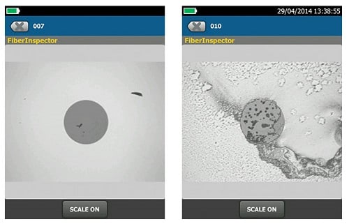
Figure 5: Specialized solvents (left) are far more effective at cleaning endfaces than IPA that can leave behind a residue (right).
The solvent itself should also be specially formulated for fiber endface cleaning, such as Fluke Networks’ Fiber Optic Solvent Pen. While isopropyl alcohol (IPA) was used for many years to clean fiber endfaces, specialized solvents have a lower surface tension that makes them far more effective at enveloping debris for removal and dissolving contaminants (see Figure 5). IPA can also leave behind a “halo” as it dries that not only causes attenuation, but also can be difficult to remove. No solvent should remain on the endface after cleaning.
To clean fiber endfaces inside ports or equipment, specially designed lint-free swabs or mechanical port cleaning devices like Fluke Networks’ Quick Cleaners are used instead of wipes (see Cleaning Kits, below). When using swabs for port cleaning, it is important to apply just enough pressure to clean the endface while rotating the swab several times in one direction. When using solvents with port cleaning, it is even more important to not use excessive solvent that can saturate the plug interface. The evaporation rate of a solvent becomes significant with port cleaning as it is harder to guarantee removal of all solvent. Lingering solvent can become trapped during mating and cultivate a harmful residue over time. This is another reason to use solvents that are specially formulated for cleaning fiber–these solvents stay around long enough to work but evaporate much faster than IPA.
It is also important to remember that these consumables are just that, meaning that once a wipe or swab is used to clean an endface, it should be immediately discarded.
Reusing a dirty wipe or swab is one of the easiest ways to spread contamination. While cleaning of jumpers and test reference cord endfaces is important, these components are also consumables that eventually fail-sometimes cleaning is not enough if these components have reached their end of life following the vendor’s specified number of insertions.
Summary
If network uptime, signal transmission performance and equipment reliability are important to your business, skimping on inspecting and cleaning fiber optic endfaces can result in dire consequences. And just because you may think you properly cleaned, does not mean you can forego inspection. Not only are best practices for fiber cleaning essential, but every endface should be carefully inspected and certified per the IEC 61300-3-35 standard prior to making a mated connection-including both endfaces and ports.
By incorporating fiber inspection and certification into your process, you can eliminate human subjectivity and quickly inspect, grade and certify fiber endfaces per the standard. In doing so, there should be no excuse for network failures due to contaminated endfaces.
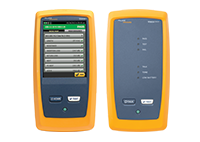
FI-7000 FiberInspector Pro Automatically Certifies Fiber EndFaces to IEC Standards
Fluke Networks’ FI-7000 FiberInspector Pro certifies fiber endfaces to the IEC 61300-3-35 industry standard in just two seconds, providing automated PASS/FAIL results that take the human subjectivity and guesswork out of fiber inspection.
Ideal for inspecting endfaces inside ports or on patch cords, the FI-7000 FiberInspector Pro detects and measures defects found on fiber endfaces and automatically certifies the results based on the IEC 61300-3-35 standard. To provide clear graphical indication of which defects pass or fail the standard’s requirements, the FI-7000’s pinch-and-zoom touchscreen colors each defect and highlights the defect’s background – defects that fail are colored Red while defects that pass are colored Green.
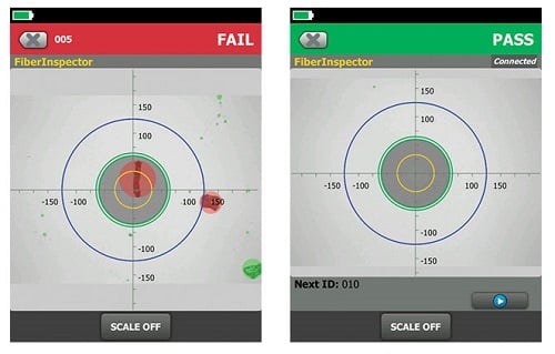
Figure 6: The FI-7000’s certification results allow you to quickly determine if the fiber endface pass or fails.
An example of a failing endface is shown on the left and a passing endface is shown on the right.
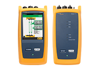
The FI-7000 is built on Fluke Networks’ Versiv Cable Certification Platform that enables storing endface images and certification in Versiv test results and taking advantage of Versiv capabilities like ProjX™ for managing job requirements, the Taptive™ user interface for easy set-up and the multifeatured LinkWare Software for managing data and generating professional test reports. The FI-7000’s PASS/FAIL fiber endface certification is available to all Versiv inspection camera owners by downloading the latest Versiv firmware.
More information at: www.flukenetworks.com/FI-7000
Fluke Networks Fiber Test Solutions
 The Versiv™ family accelerates every step of the certification process. Future-ready design supports copper certification, fiber loss, OTDR testing and hardware upgrades. The revolutionary ProjX™ management system and Taptive™ user interface ensures jobs are done right the first time. Analyze test results and create professional test reports using LinkWare management software.
Accelerates the fiber certification process with a six second two fiber / two wavelength test. Taptive user interface provides simple, animated guidance to eliminate setup errors.

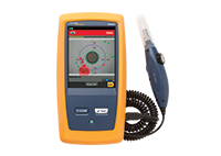
Enterprise fiber troubleshooting and certification built on the Versiv platform. Taptive user interface simplifies set up, eliminates errors and speeds troubleshooting.
The DSX-5000 CableAnalyzer accelerates every step of the copper certification process with unmatched speed for CAT 6A and Class FA. ProjX management system ensures jobs are done right the first time.
The FI-7000 FiberInspector Pro allows you to inspect and certify end-faces in 2 seconds so you can get the job done right the first time. Automated PASS/FAIL certification takes the guess work out of fiber inspection so anyone can be a fiber expert.
Versiv’s modular design provides flexibility and cost savings. Configure Versiv to meet your exact needs at www.flukenetworks.com/versivconfig
Management – LinkWare™ Live Results Management Service
Upload and consolidate Versiv test results from remote sites and track testers and project status from smart devices.
Reporting – LinkWare PC Cable Test Management Software
LinkWare Cable Test Management Software lets you manage all the results from multiple testers using one PC application.
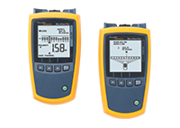
MultiFiber Pro is the only fiber tester that can test singlemode or multimode MPO fiber trunks without the use of a fan-out cords, eliminating the complexity of polarity issues, and making field testing of cassettes easier.

Easy-to-use Light Source / Power Meter (LSPM) with single-port, simultaneous dual-wavelength feature completes testing in half the time and saves measurements from both wavelengths into one record. 1490 and 1625 nm wavelengths extend product use to broader applications. Store up to 1000 results and upload to LinkWare PC.
Fiber QuickMap™ / Fiber OneShot™ PRO
One-button multimode / singlemode fiber troubleshooter locates multiple incidents in the channel in just six seconds to provide full visibility of any potentially problematic links and connections.
VisiFault™ Visual Fault Locator – Cable Continuity Tester
Visual fault locator continuity tester locates fibers, finds faults, verifies continuity and polarity.
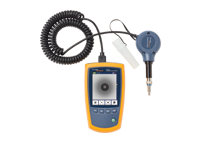
Fiber endface inspection for all types of installed fiber. Provides autofocus for a crisp image of microscopic debris and end-face damage. PortBright™ feature provides illumination in dark places.

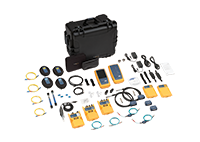
Everything you need to eliminate the #1 cause of fiber optic link failure: contamination. Supports all fiber connector types in datacenter and campus environments including MPO.


