OTDRs Are Essential for Testing and Troubleshooting Fiber Networks
Ensure the integrity of your fiber optic network with an Optical Time Domain Reflectometer (OTDR). OTDR testing analyzes fiber optic cable performance from end to end by testing components along the cable, including connection points, bends, and splices.
On This Page
- What Is an OTDR?
- Purpose of an OTDR
- Benefits of an OTDR
- Types of OTDRs
- How to Use an OTDR
- Troubleshooting with an OTDR
- Keep Learning
What Is an OTDR?
An OTDR is a powerful tool that helps technicians and engineers assess the health of fiber optic cables.
OTDRs inject high-powered light pulses into the fiber using specialized laser diodes. As these light pulses travel down the fiber, they encounter various events: connectors, breaks, cracks, splices, and the fiber's end. Such events cause a change in the refractive index, leading to reflections back toward the OTDR. These reflections, known as Fresnel reflections, are meticulously measured by the OTDR to pinpoint the location of these events within the fiber link.
Due to the inherent structure of the fiber and microscopic imperfections within the glass, a small portion of the light pulse scatters in various directions. This phenomenon is called backscattering. By measuring the returning scattered light alongside the reflections, the OTDR gathers comprehensive data on the fiber's characteristics, including attenuation (insertion loss) and potential defects.
Purpose of an OTDR
The primary purpose of an OTDR is to characterize the insertion loss of a link by comparing the difference between the amount of backscatter from the near and far ends. It also measures the amount of light reflected for each event (connectors, splices, etc.), not including the backscatter, relative to the launch pulse. This is called reflectance, expressed in decibels (dB) as a negative value. Higher values (closer to 0 dB) indicate stronger reflections, potentially due to poor connections.
Reflectance is essentially the reverse of return loss, which compares the input power to the reflected power and is always a positive number. Values further away from zero indicate better performance for both reflectance and return loss.
Benefits of an OTDR
Characterizing a fiber link with an OTDR offers several benefits.
- • A fiber link can contain several connectors and/or splice terminations that may have been performed by different technicians with varying skills. Other disturbances — such as dirty fiber end faces, macrobends, and microbends — can occur within the link due to poor workmanship or other installation factors. Characterizing the fiber with an OTDR allows technicians to pinpoint the location of any fault, identify poor installation practices, and verify the quality of the installation to ensure it supports current and future applications.
- • Characterizing a fiber link with an OTDR also allows technicians to identify questionable connection points with a high loss that may need to be addressed. This can help prevent future problems, since loss can increase over time due to poor cable management, splice degradation, dirty fiber end faces, and even loss of power from aging transmitters.
- • An OTDR also confirms precisely how many connections exist within a link. When a link contains too many connection points, it can exceed loss limits for a given application.
- • An OTDR can minimize the risk of missing a bad connection, which can happen if you are only using an Optical Loss Test Set (OLTS) to calculate total insertion loss, as required by industry standards in Tier 1 testing. Because individual event losses are invisible to an OLTS, a link can pass overall insertion loss testing and still fail to carry network traffic due to specific reflectance events.
Types of OTDRs
OTDRs are typically available as bench models or handheld devices. Bench-top OTDRs are relatively large, use an AC power source, and have highly specialized functions and features for laboratory testing. In contrast, hand-held OTDRs are smaller, lightweight, and battery-powered for use in the field.
Not all hand-held OTDRs are created equal. They have different capabilities, functionality, and features to consider. For example, an OTDR that can test both multimode and single-mode fiber at multiple wavelengths and longer distances can cover a broader range of applications. OTDRs with ultra-short event and attenuation dead zones (the distance required to make a loss measurement for an event) are better for testing short connectors and patch cords in data center environments.
Ease of use is also a consideration. Some OTDRs designed for service providers and carrier networks often contain complicated user interfaces with cumbersome multi-level menus. The most flexible OTDRs offer intuitive usability across all deployment environments — from the enterprise and data center to outside plant (OSP) and passive optical network (PON) environments. Straightforward, easy-to-use OTDRs minimize training time and speed up testing, which translates directly into cost savings.
The ability to reliably document results is another feature to consider. The Fluke Networks OptiFiber® Pro OTDR provides an easy way to deliver test results and reports — just upload results to our cloud-based LinkWare™ Live service to manage cable certification jobs and keep track of every test. With LinkWare Live, results from both an OLTS and an OTDR, and even an end face inspection camera, can be integrated into a single test report for a given project, providing complete documentation that satisfies customers and facilitates future troubleshooting.
How to Use an OTDR
OTDRs are required for Tier 2 compliance testing within TIA standards and for "extended" testing within ISO standards. They are also ideal for troubleshooting existing fiber cable plants.
OTDR Test Parameters
First, you must select the specific application's fiber type, wavelength, and test limit. Advanced OTDRs with auto-test functionality can analyze fiber runs to set key parameters for optimal viewing and results. However, there may be instances where you prefer to manually set parameters such as pulse width, averaging time, dead zones, and distance range.
For example, while a narrower pulse width can reduce the range of the OTDR, it can provide more detail in and around specific events, especially when two events are extremely close together.
Certifying New Links with an OTDR
Tier 2 testing builds upon Tier 1 by adding an OTDR to characterize individual events that are often invisible when conducting Tier 1 testing alone. Because Tier 1 testing only identifies the total insertion loss of a link and not individual events, it can miss hidden issues. For example, a very low-loss connection might mask a problematic high-loss connection. It's important to note that Tier 2 testing requires both OTDR and OLTS testing. The OLTS is required for final insertion loss verification. Combining these testers offers a complete testing strategy for fiber optic systems.
As fiber optic standards demand tighter tolerances for signal loss, precisely locating and measuring events that weaken the signal becomes even more critical. This trend is driving an increase in specifications that mandate Tier 2 testing.
Additionally, some applications require measuring the reflectance of specific connectors, which can only be done with an OTDR. For instance, in short-reach single-mode applications highly susceptible to reflectance, such as 100GBASE-DR, 200GBASE-DR4 and 400GBASE-DR4, IEEE sets loss limits based on the number and reflectance of connectors in the link.
Bi-Directional Testing with an OTDR
Bi-directional testing measures from both ends to ensure accurate measurement of total signal loss across the entire link. That's because measuring the loss of fiber connectors and splices, as well as overall link loss, depends on the test direction. Testing a fiber link in one direction delivers different results than testing the same link in the opposite direction. Accurate measurement requires averaging the results from both directions.
With the time and cost involved in testing from both ends, technicians often try to test all links from one end before moving to the other end — but this one-sided approach doesn’t work. Standards require launch and tail cords to remain in their initial measurement positions for accurate bi-directional testing.
The answer is to use a loop to connect the two fibers at the far end, allowing the link to be tested in both directions in one shot without moving the OTDR to the far end. Advanced OTDRs, like the OptiFiber Pro OTDR series, feature SmartLoop™ technology. SmartLoop checks for the presence of the launch, loop, and tail fiber during duplex testing. With SmartLoop, technicians can deploy multiple loops at the far end and perform a set of bidirectional tests without ever having to leave the near end, cutting test time by at least 50%.
Bi-directional testing on an OTDR can test fiber cables in both directions with a loop.
OTDR Trace Analysis
In the image below, the trace gradually declines due to insertion loss as light travels along the fiber and is interrupted by sharp shifts caused by connectors, splices, breaks, sharp bends, and other events. The end of the fiber can be identified by a large spike after which the trace drops dramatically down the Y axis.
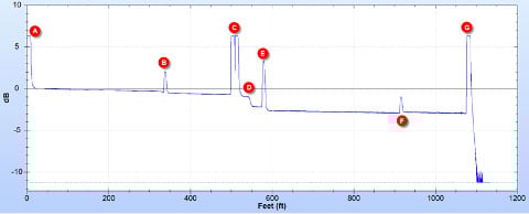
Typical OTDR trace, showing length, decline in signal strength, and events.
- The OTDR connector, which has a large reflectance that makes it impossible to characterize the loss in the first connector.
- The first connector of the link under test is characterized using a launch fiber of about 350 feet.
- Two connectors that are too close together for the OTDR to properly characterize the loss in each.
- A loss event with no reflectance, likely a bad splice or APC connector
- A typical UPC connector with reflectance and loss
- A connector with reflectance, where the signal after the connector is stronger than before. This is referred to as a "gainer" and is indicative of connecting fiber types with different backscatter properties.
- The end of the fiber, which has a strong reflection that makes it impossible to determine if there is a connector there and its performance
The ability to pinch and zoom on an OTDR trace can provide more detail about specific events.
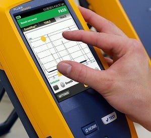
It’s easier to view trace results on an OTDR with advanced touchscreen features like pinch and zoom.
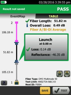
While all OTDRs display a graphical trace of the fiber links, interpreting these traces can be challenging if you're not a trace analysis expert. Advanced models like the OptiFiber Pro address this by incorporating automated analysis that translates the trace into a clear event map, pinpointing locations of connectors, splices and potential issues. The event map is ideal for technicians new to trace analysis; it offers a simplified view for easier troubleshooting and can be a valuable training tool. Unsure about a specific event on the trace? Simply switch between the detailed view and the event map to verify your interpretations and hone your trace-reading skills.
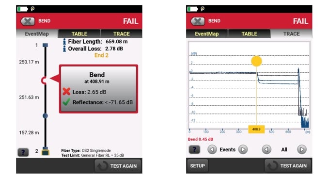
Advanced OTDRs recognize events and present them in both a trace (right) and in an easy-to-interpret manner (left).
Troubleshooting with an OTDR
Even after a fiber plant has been installed, tested, and commissioned, a fiber link may experience problems ranging from too much insertion loss, retransmits, and bit errors to not functioning at all. OTDRs are the ultimate tool for troubleshooting an existing fiber cable plant. While other tools — such as visual fault locators (VFLs), fault finders, and OLTS — can be used for troubleshooting, only an OTDR can tell you exactly where breaks, bends, or bad connections are located along the fiber link and characterize each event.
When troubleshooting with an OTDR, you have a few nuances to consider:
- • When a fiber cable has exceeded its bend radius or is kinked, you may need to test it at two wavelengths to locate this type of stress: 850 and 1300nm for multimode, and 1310 and 1550 for single-mode. At the higher wavelength, a stressed fiber will show significantly higher loss; normally, the higher wavelength would show a lower loss.
- • There may also be instances when you need to manually adjust the OTDR settings. For example, a good splice can exhibit a loss of less than 0.1 dB. If you need to locate a very low-loss splice, it may not show up on the OTDR if the loss threshold is set higher than the loss of the splice. On the OptiFiber Pro, the auto setting for Loss Threshold is 0.15dB, which means it will only find events at or above this level. Simply adjust the Loss Threshold to locate extremely low-loss splices.
The award-winning OptiFiber Pro OTDR from Fluke Networks provides the ultimate testing and troubleshooting solution to ensure the health of your most critical network cabling.
Keep Learning
Related Products
FI-7000 FiberInspector™ Pro
CertiFiber® Pro Optical Loss Test Set
MultiFiber™ Pro Optical Power Meter and Fiber Test Kits
OptiFiber® Pro OTDR Family


