WHITE PAPER
Demystifying Fiber Test Methods – Back to Basics
Download PDF
On This Page
- Fiber Optic Cable Testing Methods
- What Is Fiber Testing?
- What Are the Methods of Fiber Testing?
- What Are the Standards for Fiber Optic Cable Testing?
- What Are the Different Types of Fiber Optic Cable Testing?
- Permanent Link and Channel
- Cabling Configurations
- One-Cord Method
- Two-Cord Method
- Three-Cord Method
- Enhanced Three-Cord Method
- Equipment-Cord, Channel Test Method
- Summary
Fiber Optic Cable Testing Methods
Fiber optic networks are the backbone of modern telecommunications, providing high-speed data transmission over long distances with minimal loss. The performance and reliability of these networks depend on the quality of the fiber optic cables and the precision of their installation. This is why fiber optic cable testing is critical.
Fiber optic testing ensures the performance and reliability of fiber optic networks. These test procedures assess the physical and functional qualities of fiber optic cables, connectors, and the network as a whole. Key tests include:
- Measuring signal loss
- Verifying the strength and quality of the fiber
- Ensuring compliance with industry standards
Effective fiber testing utilizes advanced tools such as Optical Loss Test Sets (OLTS), Optical Time-Domain Reflectometers (OTDR), and Visual Fault Locators (VFL) to diagnose and correct issues, ensuring optimal network performance. Such a comprehensive approach to fiber optic cable testing safeguards the integrity of data transmission.
Fluke Networks provides comprehensive solutions for fiber optics testing, ensuring your network performs at its optimal level.
What Is Fiber Testing?
Fiber testing evaluates fiber optic cables' performance characteristics and integrity. It verifies the functionality and efficiency of newly installed and existing fiber optic networks. Careful and comprehensive fiber optics testing helps technicians detect issues such as signal loss, interference, and physical damage to the cables, any of which can severely impact network performance.
What Are the Methods of Fiber Testing?
There are several methods of fiber optic cable testing, each serving a specific purpose in assessing the cable's performance and reliability:
- Optical Loss Test Sets (OLTS): This method measures the total light loss in a fiber optic link, simulating the network conditions.
- Optical Time-Domain Reflectometer (OTDR): OTDR testing involves sending pulses of light down the fiber to detect faults, bends, and splice losses by analyzing the light scattered or reflected.
- Visual Fault Locator (VFL): VFLs use a visible light laser to identify breaks and tight bends in the fiber optic cable.
- Fiber Inspection Probes: These devices magnify the end face of a fiber connector, allowing technicians to find dirt, debris, or damage that could impede performance.
What Are the Standards for Fiber Optic Cable Testing?
Industry standards in fiber optic cable testing are crucial for ensuring a fiber optic network’s consistency, reliability, and interoperability. The key standards organizations include:
- TIA/EIA: Sets standards for fiber optic cable system design, installation, and testing in North America.
- IEC: Sets international standards covering various fiber optics testing procedures and parameters.
- ISO: Provides quality management and assurance standards, including those relevant to fiber optic testing.
What Are the Different Types of Fiber Optic Cable Testing?
Fiber optic cable testing can be categorized based on the type of test being conducted:
- End-to-End Testing: Verifies light transmission capability and signal integrity over the entire length of the cable.
- OTDR Testing: Identifies the location and severity of faults within the cable or its connectors.
- Insertion Loss Testing: Measures the loss of signal power resulting from the insertion of a device in a transmission path.
- Return Loss and Reflectance Testing: Assesses the amount of light reflected back toward the source, which can cause signal degradation.
Permanent Link and Channel
The permanent link reference plane includes the attenuation of the installed fiber and the attenuation of the two connections on either end. The link can include other connections and splices. The attenuation of the equipment cords is not included since the equipment cords are not used during the reference or attenuation measurement (see Figure 1).
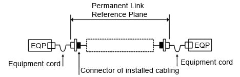
Figure 1. Permanent Link Reference Plane
The channel reference plane includes the attenuation of the installed fiber, connections, splices, and the attenuation between the equipment cords and the installed cabling which in most cases is the permanent link. The channel does not include the attenuation of the equipment cord connections coupled to the equipment (see Figure 2).
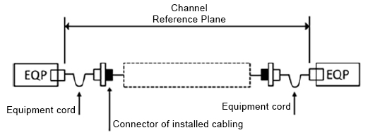
Figure 2. Channel Reference Plane
Cabling Configurations
Cabling configurations can take on these known forms:
- Adapters or sockets on both ends of the cabling
- Plugs on both ends of the cabling
- Plug on one end, adapter on the other end of the cabling
- Plugs on both ends of the cabling using equipment cords
There are five unique test methods that can be used to test the four cabling configurations:
- One-cord method
- Two-cord method
- Three-cord method
- Enhanced three-cord method
- Equipment cord or channel method
The one-cord method is used for permanent link testing and calls for the launch cord to be attached directly to the power meter for the reference and assumes the power meter has an interchangeable adapter. It is used when the cabling under test has adapters or sockets on both ends of the cabling. The one-cord method is always the preferred method when possible because it has the lowest measurement uncertainty.
The two-cord method is used for permanent link testing and can be used for two cabling configurations. First, when there are plugs on both ends of the cabling. And second, when there is a plug on one cable end and an adapter on the other end. The two-cord method essentially measures the cabling but only one end connection.
The three-cord method excludes the attenuation of both connections to the cabling under test. It may be used when pigtails are spliced onto both cable ends and directly connected into transmission equipment. This method may also be used for channel testing when better methods are not practical.
The enhanced three-cord method includes the attenuation of both connections to the cabling under test and can be used for link measurements. This method can be used for permanent link measurements when the connectors on each end of the cabling are different from each other, making the one-cord method difficult.
The equipment cord/channel test method is used when equipment cords are installed on both ends of the cabling and are awaiting connection to transmission equipment. This method is used for channel attenuation measurements. This method has lower uncertainty than the three-cord method but can be more difficult to use.
Table 1 summarizes the known attenuation measurement standards for installed optical fiber cabling, their test methods, and most importantly, when they should be used. A careful study of the table will reveal over-lap between standards. The one unique test method that is specified in only one standard is the enhanced three-cord method.
| Test Methods Defined by Standards | |||
|---|---|---|---|
| Standard | Test Methods | When Used | Comment |
| TIA-526-14-C, adaption of IEC 61280-4-1, edition 2 | One-cord | Required test method for links when adapters are attached to plugs or sockets at both ends of the cabling. | |
| Two-cord | Required test method for links with mixed connectors on both ends of the cabling, where one end is terminated with an adapter and the other end is terminated with a plug | ||
| Three-cord | Required test method for links with plugs on both ends of the cabling. | ||
| IEC 61280-4-1, edition 3 in revision | One-cord | Required test method for link when adapters are attached to plugs or sockets to both ends of the cabling. | Assumes the connector on the power meter is compatible with the cabling under test into which the launch cable is connected (power meter has interchangeable adapter). |
| Two-cord | Required test method for links that have plugs on both ends of the cabling; Required test method for links with mixed connectors on both ends of the cabling, where one end is terminated with an adapter and the other end is terminated with a plug | ||
| Three-cord | Link testing as the alternate method for the one-cord, three-cord, and equipment cord methods. | ||
| Equipment-cord | Required test method for links with plugs on both ends of the cabling utilizing equipment cords | Mostly a variant of the 1-cord method. | |
| TIA-526-7, adoption of IEC 61280-4-2, edition 2 | One-cord | Required test method for link when adapters are attached to plugs or sockets to both ends of the cabling. | Straight adoption, no adaptation so contents from IEC 61280-4-2 are the same. |
| Two-cord | Required test method for links with mixed connectors on both ends of the cabling, where one end is terminated with an adapter and the other end is terminated with a plug | ||
| Three-cord | Required test method for links with plugs on both ends of the cabling. | ||
| TIA-568.3-D | As specified in TIA 526-7 and TIA 526-14. | Channel testing should use the three-cord method as defined by IEC standards, not ISO/IEC test standard. | One-cord method is preferred for both multimode and single-mode links. |
| ISO/IEC 14763-3, edition 2 | One-cord | Link attenuation when the cabling under test has the same interface as the power meter; measures the permanent link. | Amendment in process |
| Enhanced three-cord | Link attenuation when the cabling under test has different connectors on each end of the cabling; measures the permanent link. | ||
| Channel | Channel attenuation using equipment (customer) cords excludes connections to equipment (transceivers); measures the channel. | ||
| ARINC 805 | One-cord for multimode and single-mode | Required test method | Based on TIA-526-7 (SM) and TIA-526-14 (MM) |
Permanent link test includes the attenuation of both connections on each end of the cabling under test. Channel test does not include that connection attenuation between the equipment cord and transceiver.
One-Cord Method
a. Set a reference between the light source and power meter using the launch cord (see Figure 3).
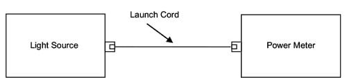
Figure 3. Set the reference
a. Attach a tail cord to the power meter.
b. Attach the launch cord and tail cord to the cabling under test (see Figure 4).
c. Make the measurement and compare to the reference measurement
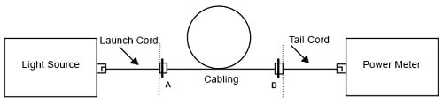
Figure 4. Measure attenuation of cabling, A connection, and B connection
Two-Cord Method
a. Set a reference between the light source and power meter using the launch and tail cord (see Figure 5).
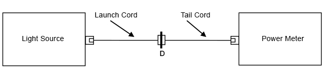
Figure 5. Set the reference
b. Make the measurement and compare to the reference measurement (see Figure 6a and Figure 6b).
c. For case 2, an adapter cord becomes part of the launch cord (see Figure 6b)
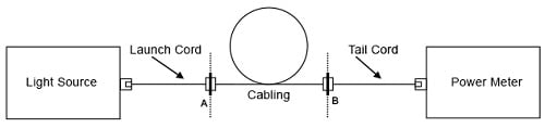
Figure 6a. Measure attenuation for case 1 (plug-adapter and plug on cabling ends)
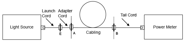
Figure 6b. Measure attenuation for case 2 (both ends of cabling are socketed)
Three-Cord Method
a. Set a reference between the light source and power meter using the launch cord, substitution cord, and tail cord (see Figure 7).
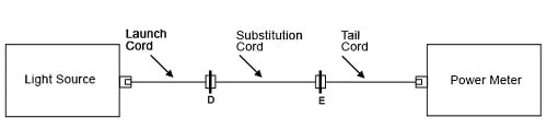
Figure 7. Set the reference
a. Remove the substitution cord and replace with the cabling under test.
b. Make the measurement and compare to the reference measurement (see Figure 8).
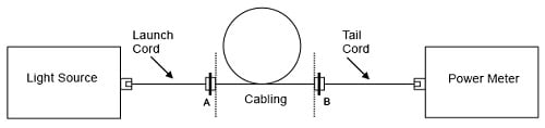
Figure 8. Measure attenuation
Enhanced Three-Cord Method
a. Set a reference between the light source and power meter using the launch cord (see Figure 9).
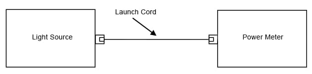
Figure 9. Set the reference using the one- cord
a. Add a tail cord to the power meter and a substitution cord between the launch and tail cords and check for low loss connections such as 0.4 dB for single-mode (see Figure 10).
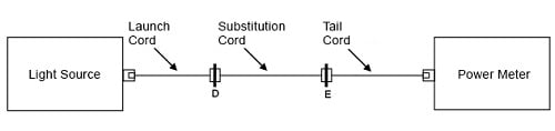
Figure 10. Check for low loss connections
a. Remove the substitution cord and replace with the cabling under test.
b. Measure the attenuation of the cabling and compare to the reference (see Figure 11).
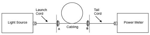
Figure 11. Measure attenuation
Equipment-Cord, Channel Test Method
a. Set the reference using the launch cord and first equipment cord attached to the light source (see Figure 12).
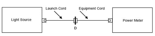
Figure 12. Set the reference
a. Add the second equipment cord to the power meter.
b. Attach the equipment cords to the cabling and measure attenuation (see Figure 13).
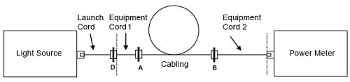
Figure 13. Measure the attenuation
Summary
Understanding the difference between a permanent link and channel can be a challenge, and knowing which test method to apply is confusing especially for hybrid configurations. These hybrid configurations do exist and understanding how to test them is a benefit for installers. There are many standards available for testing but standards also overlap for the test methods. Table 1 provides a useful outline of the various standards, which test method should be used, and which method should be applied based on cabling configuration. While there are other test methods available, Fluke Networks continues to recommend the one-cord method for all testing.
Learn more about fiber optic testers, tools, and troubleshooting on our Fiber Optic Testers page.


