OptiFiber Pro vs. Softing FiberXpert 5000 OTDR
Foreword:
This is a guide only. We'd rather you see the OptiFiber® Pro and Versiv Platform in person to understand why it's the choice of cabling professionals throughout the world. Always insist on a full demonstration of the product, including the computer software and any remote data transfer service. If you are getting a demonstration, make sure the OptiFiber Pro has the latest Version 4.8 Build 1 code and LinkWare PC Version 9.6.
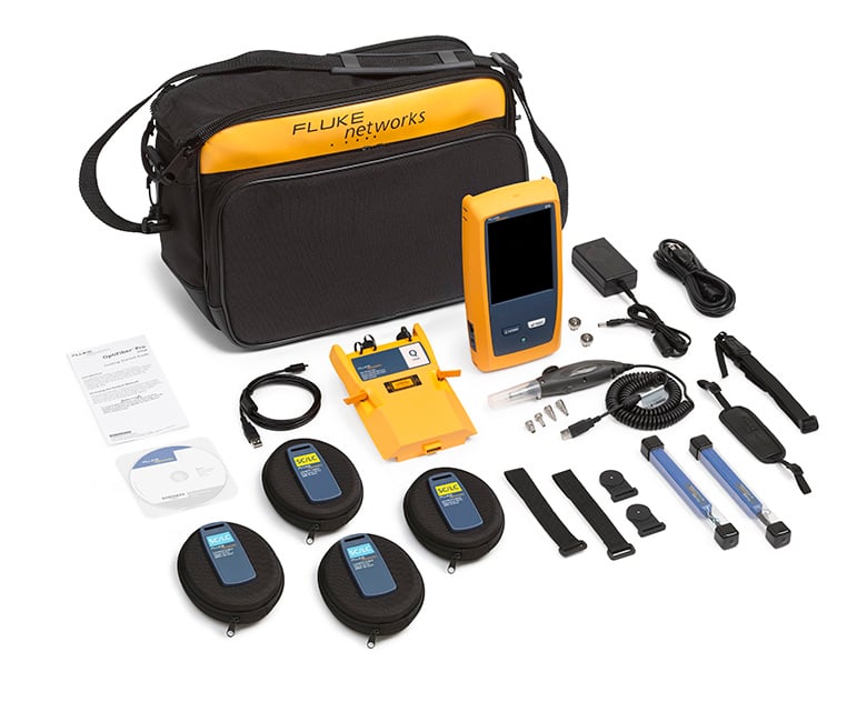
As with all OTDRs, it is important to understand what comes with the unit. Don’t assume it comes with launch cords and a camera.
This article is accurate to the best of our knowledge, derived from hands on experience and published data sheets. All information is subject to change. If you should find an inaccuracy, please do not hesitate to let us know kbfeedback@flukenetworks.com
The FiberXpert is sold under Psiber Data Systems Inc. and Softing.
|
|
OTDR Certification |
||
|
|
OptiFiber® Pro |
FiberXpert 5000 Quad |
|
|
LinkWare™ PC |
eXport |
||
|
Memory (OTDR traces) |
Up to ≈ 5,000 |
Up to ≈ 1,000 |
|
|
LinkWare™ Live |
- |
||
|
EventMap™ |
- |
||
|
SmartLoop™ |
- |
||
|
Included in LinkWare PC |
- |
||
|
ProjX™ |
- |
||
|
Included |
- |
||
|
Included |
- |
||
|
Included |
Optional |
||
|
End-face inspection camera |
Included |
Optional |
|
|
≈ 1 seconds |
≈ 6 seconds |
||
|
425 μm x 320 μm |
Not stated |
||
|
Real time trace |
Included |
Included |
|
| Optional modules |
Copper certification |
- |
|
|
OLTS certification |
- |
||
|
Active network testing |
- |
||
|
Standards based testing (PASS/FAIL) |
Included |
Included |
|
|
Dynamic range (850 nm, 1300 nm, 1310 nm, 1550 nm) |
28 dB, 30 dB, 32 dB, 30 dB |
26 dB, 24 dB, 37 dB, 35 dB |
|
|
Pulse widths |
Multimode |
3 ns to 1,000 ns |
3 ns to 1,000 ns |
|
Singlemode |
3 ns to 20,000 ns |
3 ns to 20,000 ns |
|
|
Dead zones |
Multimode @ 850 nm |
0.5 m |
0.8 m |
|
Singlemode @ 1310 nm |
0.6 m |
0.9 m |
|
|
Dead zones |
Multimode @ 850 nm |
2.5 m |
4.0 m |
|
Singlemode @ 1310 nm |
3.6 m |
4.0 m |
|
|
Linearity |
± 0.03 dB |
± 0.03 dB |
|
|
Reflection accuracy |
± 2 dB |
± 2 dB |
|
|
Highest resolution |
3 cm |
4 cm |
|
|
Screen |
Projected capacitance |
Capacitive |
|
|
Display size |
5.7 in (14.5 cm) |
5 in (12.7 cm) |
|
|
Dimensions with module inserted |
11.1 in x 5.2 in x 2.5 in
(28.2 cm x 13.2 cm x 6.4 cm) |
6.9 x 5.4 x 3.2 in
(17.5 x 13.8 x 8.0 cm) |
|
|
Li-ion ≈ 8 hrs. |
Li-Polymer ≈ 8 hrs. |
||
PC Software
Fluke Networks’ LinkWare PC Software is renowned for its ease of use and professional reporting capabilities. For existing DTX CableAnalyzer customers, LinkWare PC 9.6 provides a seamless transition to the OptiFiber Pro OTDR and Versiv family of testers. Fluke Networks’ LinkWare 9.6 Software will open any LinkWare file created since its launch back in 2002. LinkWare PC is extremely popular for its support of multiple testers including the DTX CableAnalyzer with all of its fiber module options, CertiFiber Pro, OptiFiber Pro, SimpliFiber Pro and MultiFiber Pro MPO/MTP tester. Its ability to merge Tier 1 (OLTS), Tier 2 (OTDR) and fiber inspection analysis into one concise record/report assures customers that their fiber optic installation is a cut above the rest. 
Remote transfer serice
LinkWare Live Essentials allows users to transfer results from the field to their LinkWare Live account – for free; without the use of a PC. LinkWare Live Essentials offers 10 GB of remote storage, where results/projects can be tracked on your smartphone, tablet, PC or any device with an internet browser and web connection. Results can then be pulled down into the current LinkWare PC Software on your Windows® computer, producing the exact same high quality reports you generate today.
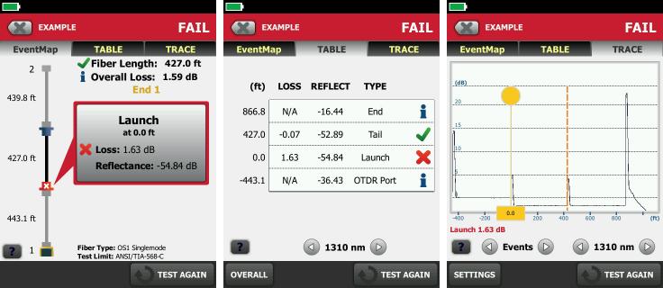
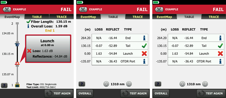
Automated OTDR Analysis
Correctly interpreting an OTDR trace is not for the faint hearted and unless you are an expert, you can often miss issues with the fiber link being tested. EventMap shows a diagram of the events on the fiber, the fiber length in feet or meters, and the overall loss of the fiber. Less skilled operators can use this screen to quickly locate connectors and faults on the fiber. For advanced users, the traditional OTDR traces are still available tapping on the TRACE tab. One improvement over your existing OTDR is that you can pinch and zoom in on the OTDR trace eliminating the need to use multiple function keys to zoom in on a event.
Bi-directional-testing from one end
More and more specifications are calling out bi-directional averaging. Walking the OTDR from one end to the other is not efficient. Some vendors offer a solution where you can use two OTDRs at the same time to achieve a quicker bi-directional test. SmartLoop allows the operator to keep the OTDR and one end negating the need for another OTDR and the walking of the OTDR to the far end. It requires no additional manipulation of the traces either in the OTDR or in the software on the PC. SmartLoop OTDR further enhances the ease and speed of testing in environments where the far end is difficult of even dangerous to reach because the OTDR never has to be moved to the far end.
Bi-directional-averaging
Taking the average of the event loss in both directions results in a more accurate loss assessment as opposed to only measuring in one direction. With your results imported into LinkWare PC, simply click on Utilities > Average Bi-Directional OTDR results and LinkWare PC creates a new test record with your averaged results.
Project management
ProjX™ System manages jobs from setup to systems acceptance, ensuring that all tests are completed correctly. Enter the testing details for a job once, and ProjX™ stores them in a project file with a name the whole team can understand. You can change modules or jobs without having to re-enter details. Additionally, you can support multiple testers on the same job by sharing test limits, cable types, and test results via USB stick, e-mail or LinkWare Live Professional, our cloud service. Easy just met efficient.
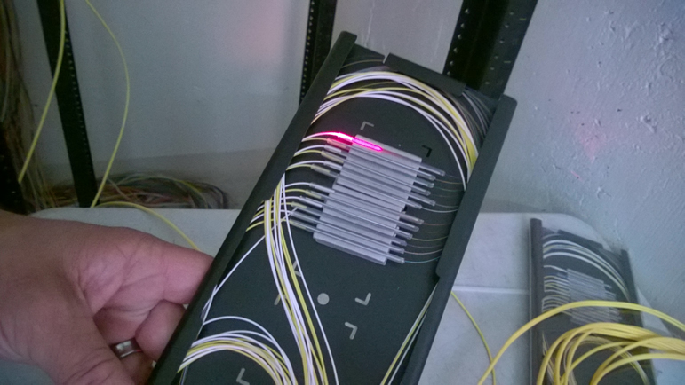
Launch and tail fibers
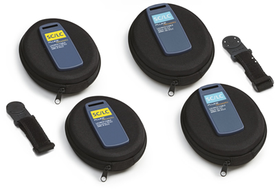
Using a 3 m (10 ft.) patch cord results in the OTDR failing to the assess the loss of the first event. This is why you must use a launch fiber. A multimode launch fiber is typically around 105 m (345 ft.) and 160 m (525 ft.) for singlemode when testing links up to ≈ 30 km (19.6 miles). The next generation of cabling standards have mandated the use of a tail fiber in order to allow the averaging of OTDR results for a more accurate loss assessment of events. OptiFiber Pro comes with two 50/125 and 9/125 SC to LC launch fibers. Along with LC OTDR port adapters, you can OTDR LC or SC links out of the box for both multimode and singlemode links. The new compact design of the Fluke Networks’ launch fibers has proven to be very popular.
Launch and tail compensation
If you add a 105 m (345 ft.) launch and tail fiber to the link you are testing, the OTDR will of course report the overall length 200 m (656 ft.) longer than the actual link itself. The launch and tail compensation feature in the OptiFiber Pro allows the OTDR to automatically remove the length of the launch and tail fibers at the time of test, negating the need to manipulate the OTDR traces later on in the PC software.
VFL
A visual fault locator is a Class 2 laser using a 650 nm source (visible light) allowing the operator to:
-
See high-loss bends. If you can see the light from the VFL at a bend in a fiber, the bend is too sharp.
-
See breaks and bad splices. These faults cause the fiber to emit red light.
-
Quickly verify the continuity of fibers.
-
Identify the polarity of duplex connections.
-
See connectors that have damaged fibers inside. A damaged fiber inside a connector causes a red light in the connector.
The OptiFiber Pro module has a built in VFL at no cost.
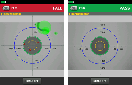
Automated end face inspection (IEC 61300-3-35)
End face inspection is critical. Although the one click style cleaning pens are convenient, they do not guarantee a clean end face, especially when the dirt or debris is embedded in the end face. The end face inspection system on the Versiv main frame allows the installer to document the clean and damaged free connectors at the end of the job – call backs for damaged connectors are now billable. (End face images can be stored within the Versiv main frame. Use the same Cable ID as the link you are OTDR or OLTS testing and Versiv will automatically add that image to your OTDR or OLTS result) The downside to inspection is the argument as to what is an acceptable end face image. Thankfully, there is a published standard in IEC 61300-3-35 that defines the level of dirt and scratches allowed on an end face. The Versiv main frame can analyze and end face image in accordance with IEC 61300-3-35 in around one second. Often quicker than an operator can decide. The PASS/FAIL can then become part of the overall test report.
Field of view for end face inspection
You will still see some specifications for video scopes calling out magnification, which is incorrect. Why? Because the magnification depends on the size of the screen the end face is being displayed on. Hence the term “field of view” which is found in IEC 61300-3-35.
Optional Modules
Not being limited to fiber testing is one of the many features that makes the Versiv platform so successful/popular. Having to learn multiple interfaces across different testers is not only wasteful in time, it often leads to errors. The Versiv mainframe can accept both copper and fiber certification modules, accelerating acceptance of installations.
Battery
One big improvement over previous testers is that in unlikely event the battery develops a fault, the unit can still be operated when connected to a power supply. If a Li-Polymer battery is left fully discharged for a period of time then charged, the battery can physically expand with the potential of causing damage to the instrument. Users of radio controlled cars are very familiar with this phenomenon.


