Overview
Multi-fiber push on connectors, or MPOs for short, are fiber connectors comprised of multiple optical fibers. While defined as an array connector having more than 2 fibers, MPO Connectors are typically available with 8, 12 or 24 fibers for common data center and LAN applications. Other fiber counts are available such as 32, 48, 60 or even 72 fibers, but these are typically used for specialty super high-density multi-fiber arrays in large scale optical switches.
You may also see the term MTP Connector used interchangeably with MPO Connector. The term MTP is a registered trademark of the MPO connector offered by US Conec. The MTP connector is fully compliant with MPO standards and is described by US Conec as an MPO that has been engineered to very tight tolerances for improved performance. For the purposes of this discussion, we will refer to only MPO connectors since MTPs are considered to be MPO connectors.
Contents
Certification and Standards
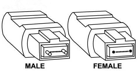 Just like other standards-based connector interfaces, manufacturers of MPO Connectors must comply with intermateability standards. For MPO Connectors, these include IEC 61754-7 and EIA/TIA-604-5 (FOCSI 5) standards that specify the physical attributes of the connector, such as pin and guide hole dimensions for male and female interfaces. These standards ensure that any compliant plugs and adapters can be intermated and meet a certain level of performance.
In addition to intermateability, MPO Connectors also must meet specific end face geometry parameters defined by the IEC PAS 61755-3-31 fiber optical interface standard. These include angle of polish, fiber protrusion height and maximum fiber height differential across all fibers in the array and for adjacent fibers. The overall performance of the connector significantly depends on controlling these mechanical characteristics. For example, if the fiber height differential is exceeded and fibers in the array are not of equal height, some fibers will not achieve proper mating. This can significantly impact insertion loss and return loss.
Use and Application
MPO Connectors have been used in duplex 10 Gig fiber applications throughout the data center for several years as a way to deploy preterminated plug and play backbone cables between switches that take up less pathway space and ease cable management while offering faster deployment. In these 10 Gig applications, 12-fiber or 24-fiber trunk cables with MPO connectors on both end form the permanent backbone link and are then transitioned to duplex fiber connectors at patch panels via either MPO-to-LC cassettes or MPO-to-LC hybrid patch cords.
As the need for bandwidth speeds pushed beyond 10 Gig, the MPO connector became the de facto interface for higher speed switch-to-switch backbone data center applications using parallel optics. For example, 40 Gig and 100 Gig applications (40GBASE-SR4 and 100GBASE-SR4) over multimode fiber use 8 fibers with 4 transmitting at either 10 Gbps or 25 Gbps and 4 receiving at either 10 Gbps or 25 Gbps. These common data center applications require an 8- or 12-fiber MPO connector (only 8 of the 12 fibers are used when using 12-fiber MPOs). Looking ahead, standards bodies are anticipating even higher speeds of 200 and 400 Gig also being supported by MPO connectors and parallel optics. The MPO connector interface is therefore here to stay.
Cleaning and Inspecting
Every fiber end-face should be cleaned and inspected, and MPO Connectors are no different. In fact, cleaning and inspecting can be even more of a concern for MPO Connectors due to the larger surface area. When cleaning these larger surface areas, it is much easier to move contaminants from one fiber to another within the same array. And the larger the array, the higher the risk. With a greater number of fibers, such as with 24- or 32-fiber MPO Connectors, the height differential of fibers is more difficult to control and height variances across the fibers can increase the risk of not every fiber being properly and equally cleaned. That’s why it is critical to inspect, clean and always inspect again.
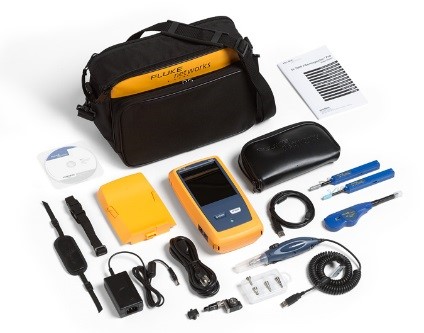
The FI-7000-MPO kit comes with an MPO inspection tip and an MPO Quick Clean Cleaner
When it comes to inspecting fiber end faces, the IEC 61300-3-35 “Basic Test and Measurement Procedures Standard for Fiber Optic Interconnecting Devices and Passive Components” contains specific cleanliness grading criteria to assess pass or fail certification for inspection of a fiber end-face, removing the human subjectivity factor and avoiding any disputes. For various connector types and fiber size, IEC 61300-3-35 certifies the cleanliness of a fiber end face based on the number and size of scratches and defects found in each region of the end face, including the core, cladding, adhesive layer and contact zones.
Fluke Networks’ FI-7000 FiberInspector Pro certifies fiber end-faces to IEC 61300-3-35 industry standards in just over a second, providing automated PASS/FAIL results. And Fluke Networks’ FI-7000-MPO kit comes with an MPO inspection tip and an MPO Quick Clean Cleaner to make it easier than ever to ensure clean MPO connector end faces
Polarity
For fiber links to properly send data, the transmit signal (Tx) at one end of the cable must match the corresponding receiver (Rx) at the other end. The purpose of any polarity scheme is to ensure this continuous connection, and this becomes a bit more complex when dealing with multi-fiber components. Industry standards call out three different polarity methods—Method A, Method B and Method C. And each method uses different types of MPO cables.
Method A uses Type A straight-through MPO trunk cables with a key up connector on one end and a key down connector on the other end so that the fiber located in Position 1 arrives at Position 1 at the other end. When using Method A for duplex applications, making the transceiver-receiver flip is required in a patch cord at one end.
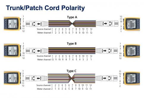
Method B uses key up connectors on both ends to achieve the transceiver-receiver flip so that the fiber located in Position 1 arrives at Position 12 at the opposite end, the fiber located in Position 2 arrives at Position 11 at the opposite end and so on. For duplex applications, Method B uses straight A-B patch cords on both ends.
Method C uses a key up connector on one end and a key down on the other end like Method A, but the flip happens within the cable itself where each pair of fibers is flipped so that the fiber in Position 1 arrivers at Position 2 at the opposite end and the fiber in Position 2 arrives at Position 1. While this method works well for duplex applications, it does not support parallel 8-fiber 40 and 100 Gig application and is therefore not recommended.
With three different polarity methods and the need to use the correct type of patch cords for each, deployment mistakes can be common. Thankfully, Fluke Networks’ MultiFiber™ Pro allows users to test individual patch cords, permanent links and channels for correct polarity.
Performance Testing
Just like any fiber link in the data center, those that use MPO connectors still need to be tested to ensure that they remain within insertion loss budgets. This is especially true for higher speed 40 and 100 Gig applications that require the use of MPOs. Since these applications have much lower loss budgets, it’s important to ensure the highest testing accuracy as possible.
Before Fluke Networks’ MultiFiber Pro tester with on-board MPO connectors was available, MPO-based fiber links were tested with a traditional duplex fiber tester. This was extremely time consuming, requiring the use of MPO to LC fan-out cords that separate the multiple fibers into single fiber channels and the need to verify test reference cords before connecting each of the fiber pairs to be tested on both ends. This complex testing also lead to greater inconsistencies and made it more difficult to keep all the fibers clean during the process.
With the ability to scan all 8, 10 or 12 fibers of an MPO Connector simultaneously, it is highly recommended to use a tester like the MultiFiber Pro with an on-board MPO connector that eliminates complexity and tests 90% faster than using a duplex tester. In fact, the IEC TR 61282-15 Ed1 “Cable plant and link – Testing multi-fibre optic cable plant terminated with MPO connectors” approved in February 2017 requires that testers must have an MPO interface when testing these systems.
Contact Us
U.S. / Canada: 1-800-283-5853
International: 1-425-446-4519
info@flukenetworks.com
Gold Maintenance and Support Program
Related Products

FI-3000 / FI2-7300 FiberInspector™ Ultra Camera
FI-7000 FiberInspector™ Pro
MultiFiber™ Pro Optical Power Meter and Fiber Test Kits

Fiber Optic Cleaning Kits


