101 Series: What is an APC Connector and How Do I Test It?
October 11, 2018 / General, 101 learning, Installation and testing, Upgrading and troubleshooting, Best Practices
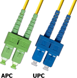
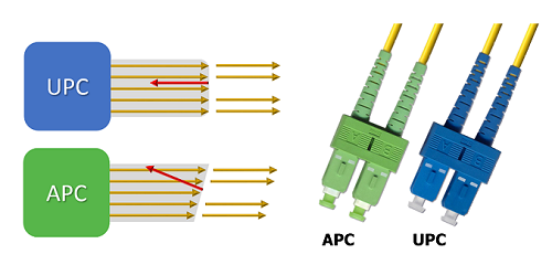
The singlemode fiber connectors you likely encounter the most feature a blue connector body, but if you’re working with any passive optical networks (PONs), carrier networks or large cloud/colo or hyperscale data centers, you may encounter singlemode fiber connectors with a green connector body – and these green connectors are growing in popularity.
Blue singlemode connectors feature a UPC (ultra physical contact) fiber endface, while green singlemode connectors feature an APC (angled physical contact) fiber enface. And yes, it’s important to understand the difference – especially when it comes to testing.
Angle for Performance
With a UPC connector, the fiber endface is a slightly rounded surface. In contrast, the endface of an APC connector is slanted 8 degrees. The slight angle causes reflected light to be absorbed into the cladding, thereby reducing back reflections in the fiber core and offering superior return loss performance.
While it is usually insertion loss that we care about with fiber links, there are some applications that are much more susceptible to return loss. For example, the high-power lasers used in long haul fiber links are very sensitive to reflections, and they can even be damaged by severe reflections. Fiber applications that operate at higher wavelengths (typically 1500 nanometers and up) are also more susceptible to reflections, including wavelength division multiplexing (WDM) applications that use multiple wavelengths to send signals and applications that use RF signals for sending video over higher wavelengths, including PONs/GPON deployments.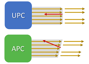
These applications explain why we see APC connectivity deployed in service provider networks and FTTX applications. And as more enterprise customers deploy PONs for their LANs, more cable companies shift to delivering broadband services over fiber and more data centers connect to carrier networks and deploy longer singlemode links and WDM applications, we are starting see increased use of the APC connector and in a broader range of environments.
It’s important to note that UPC and APC connectors cannot be mated. Not only will the fiber cores not line up and cause very poor performance, but if you try to mate the two, you can cause damage to the endface –including the endface used in critical (and expensive) fiber transmitters.
Testing All the Angles
When it comes to testing singlemode fiber systems using APC connectivity, there are a few things you need to know. When conducting Tier 1 insertion loss testing, Fluke Networks’ CertiFiber® Pro accepts APC connector in the INPUT port ONLY – the OUTPUT port uses a UPC connector. While no damage will occur, you will get a warning from the tester about the received power being too low. The INPUT port is non-contact mating so it can accept either connector type. So when testing APC systems, you will need two hybrid UPC-to-APC cords and two APC-to-APC cords to make the connection.
And if you’re inspecting an APC connector with Fluke Networks’ FI-700 FiberInspector Pro or FI-500 FiberInspector Micro, you need to use the APC probe tip (purchased separately). If you try to use the UPC probe tip for inspecting an APC endface, you will not be able to focus in on the core and endface. On the other hand, the geometry of the APC probe tip will accommodate the 8-degree angle of the APC endface so you get proper viewing.
Recent Posts See All >
What Is Fiber Optics? A Guide
2024-03-20
Choosing Stranded vs. Solid Wire Cable
2024-03-06
What Is Return Loss?
2023-02-14
More General Posts See All >
What Is Fiber Optics? A Guide
2024-03-20
Choosing Stranded vs. Solid Wire Cable
2024-03-06
What Is the Right Way to Test an MPTL?
2023-08-22
Explore Our Products
FI-500 FiberInspector™ Micro Fiber Optic Scope Camera
FI-7000 FiberInspector™ Pro
CertiFiber® Pro Optical Loss Test Set


©2006-2021 Fluke Corporation。保留所有权利。
RM2011, 20/F, SCITECH Tower, 22 Jianguomenwai Avenue, Chaoyang District, Beijing, China
地址:北京市朝阳区建国门外大街22号赛特大厦20层2011室
联系电话:400-8103435
沪ICP备11037028号-15![]()