Reflectance and Optical Return Loss (ORL) Measurement and Testing - OptiFiber
Beginning with software release 1.8, OptiFiber is able to measure optical return loss. Optical return loss for individual events, i.e. the reflection above the fiber backscatter level, relative to the source pulse, is called reflectance. Optical return loss is given in units of dB and always a negative value for passive optics, with values closer to 0 representing larger reflections (poorer connections).
Return loss for the entire fiber under test, including fiber backscatter and reflections and relative to the source pulse, is called Optical Return Loss (ORL). It is also given in units of dB, but always a positive value, with values closer to 0 dB representing more total light reflected.
This document discusses the limitations on these optical return loss measurements.
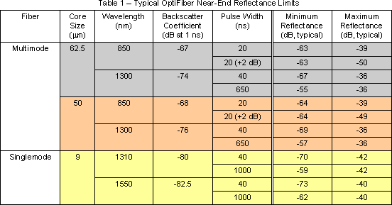
There is a limit to the range of values that can be measured for optical reflectance. The maximum optical reflectance is limited by where the signal saturates at the top of the trace. The minimum optical reflectance is limited by where the signal is too small relative to the noise to be detected. Likewise, ORL is limited when any part of the signal saturates or the entire trace is not captured (such as when there is insufficient dynamic range).
The limits listed are typical. The range for measuring optical reflectance depends on a number of factors wavelength, pulse width, backscatter coefficient, attenuation, and dynamic range.

The limits listed in the table are based on using the default FOTP-8 values for backscatter coefficient. Using different values should not affect the maximum limits much if the backscatter coefficient value is accurate for the fiber being tested and the backscatter level is at least 2 dB below the saturation level (top of the trace).
For the minimum limit of the reflectance, the backscatter coefficient has a direct impact, as can be seen by comparing 62.5 mm to 50 mm fiber. However, as the backscatter level nears the noise floor (bottom of the trace), increased noise limits the detection of small reflections.
The term near-end implies negligible fiber attenuation, which is expected for reflections near the OTDR port (say, within 100 meters) with good connections and low insertion loss and little fiber attenuation. At longer distances, higher reflectances can be measured. As an extreme example, for single-mode fibers using the widest pulse width (1000 ns), a reflection that has its backscatter level near the noise floor could be measured as high as about -20 dB. However, when the backscatter level is within 5 dB above the noise floor, smaller reflections become hidden in the noise. Reflections at the noise floor level have a minimum limit as much as 7 dB higher than listed in the table.
The noise floor level depends on the dynamic range (initial backscatter level above the noise floor), which can vary some between instruments. The maximum reflectance depends on where the initial backscatter level is relative to the saturation level (top of trace). This also varies some between instruments. The values listed in the table are for typical instruments.
Typical Reflectances
As a comparison, here are some typical reflectances:
- Fiber end with flat cleave: -14 dB
- Good multimode PC connection: -35 dB or lower
- Good singlemode PC connection: -50 dB or lower
- Good angle-polish connection: -60 dB or lower
- Good fusion splice: -60 dB or lower
Viewing Reflectance and ORL
The ORL can be found by pressing F3 View Details and paging down the screen. To see Reflectance, press F3 to view individual events and scroll down the page.
The best low-reflectance connector is the angle-polished connector (APC). APC connectors specify reflectance of -65 dB or better. Low-reflectance connectors are important throughout the system and not strictly for the front end. The front-end connector, however, does not isolate strong reflections from other reflective components; rather, it simply does not contribute a significant reflected signal itself.


