Settings for OTDR Tests - DTX Compact OTDR Module
Setting up for a DTX OTDR Test using the DTX Compact OTDR Module:
To access the settings for OTDR Tests, turn the rotary switch to SETUP; then select Fiber OTDR. Use LEFT ARROW, RIGHT ARROW to move between tabs.
To see the limits used for an OTDR test, press F3 View Limits from the OTDR Results screen.
To see the settings used for an OTDR test:
- On the OTDR Results screen, press F2 View Events.
- On the Event Table screen, press F3 View Details.
- On the Overall Results screen, press F1 OTDR Settings.
The settings used may be slightly different from the nominal values selected on the OTDR tab.
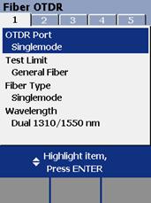
Figure 1. OTDR Test Settings - Tab 1
Figure 1 above displays the Fiber OTDR Settings in Tab 1, which include:
- OTDR Port: Select Multimode or Singlemode to view or edit those settings.
-
Test Limit: The tester compares the OTDR test results to the selected test limit to produce PASS/FAIL results. You can select factory-installed limits or custom limits.
-
Fiber Type: Select a fiber type that is appropriate for the fiber you will test. You can select factory-installed fiber types or custom types.
-
Wavelength: You can test cabling at one or all the wavelengths supported by the installed module and the selected test limit.
Note
If you select the dual-wavelength setting, be sure to select a fiber type and test limit that supports both wavelengths.

Figure 2. Fiber OTDR Settings - Tab 2
Figure 2 above displays the settings for the OTDR Tests in Tab 2, which include:
- Launch Compensation: Lets you remove the effects of launch and receive fibers from OTDR results.
-
Testing From: The cable end where the tester is located. Based on this setting, the tester labels OTDR results as End 1 or End 2 to indicate which end of the cabling you tested.
-
End 1, End 2: Names you assign to the ends of the cabling. The names are saved with OTDR results.

Figure 3. Settings for the OTDR Tests - Tab 3
Figure 3 above displays the settings for the OTDR Tests in Tab 3, which include:
-
Fiber Characteristics: When Fiber Characteristics is set to User Defined, the n and Backscatter values can be edited by the user. When the Fiber Characteristics is set to Default, the tester uses the values defined in the current Fiber Type.
-
n: The n value is the index of refraction. Index of refraction is used to calculate length. The default n values defined in the fiber types are suitable for most applications. Minor differences between the default n and a fiber's actual n usually do not make enough difference in length to fail a fiber. Increasing n decreases measured length.
-
Backscatter: Backscatter is the backscatter coefficient, which indicates the amount of light the fiber reflects back to the OTDR (using a 1 ns pulse). This value is used to calculate event reflectance for OTDR tests. Enter the backscatter coefficient of the fiber under test, if known. This value is specified by many fiber manufacturers.
Figure 4 and 5 below display the settings for the OTDR Tests in Tabs 4 and 5:
Tab 4
Note
These settings apply only in Manual OTDR mode.

Figure 4. Settings for the OTDR Tests - Tab 4
- Range: The range setting determines the maximum distance shown on the trace.
-
Averaging Time: The averaging time sets the number of measurements averaged together to create the final trace.
Tab 5
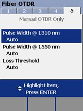
Figure 5. Settings for the OTDR Tests Tab 5
-
Pulse Width
-
Loss Threshold (Auto or User Defined):
-
Auto sets the threshold to the default value of 0.15 dB.
-
User Defined lets you set the threshold (in decibels) for reporting loss events.
-
Learn About:
- OTDR, Fiber Testing


