APPLICATION NOTE
How to Use the CertiFiber® Pro to Test Installed Corning Multimode Pretium EDGE® Tap Modules
Download PDF
Overview
The Corning Pretium EDGE® Tap Module allows passive tapping into optical networks for monitoring purposes. The modules contain splitters that divide each optical signal into two outputs, one for network link traffic and one for monitoring. To ensure that the installed module operates correctly and to meet the requirements for Corning warranty coverage, you must measure the loss of the network links with the module installed. Optionally, you can also measure the loss of the tap links from the module to ensure that the links to your monitoring equipment operate correctly.
Note these important points regarding measuring loss through an EDGE Tap Module:
- Because the splitters in the tap module have low loss in one direction and high loss in the other direction, you measure loss through the module in one direction only (no bi-directional tests).
- The splitters in the multimode tap modules are optimized for 850 nm VCSEL (Vertical-Cavity Surface-Emitting Lasers), so you test at only 850 nm.
- The network links through the LIVE port on the tap module to the EDGE module at the far end are duplex, so you test them with the CertiFiber Pro in Smart Remote mode. The links through the TAP port are all outputs, so you test them with the CertiFiber Pro in Far End Source mode.
On This Page
- Required Equipment
- Calculating the Loss Budgets
- Setting Up a Custom Test Limit
- Testing the Network Links
- Set the Reference for Smart Remote Mode
- Test the Network Links in Smart Remote Mode
- Testing the Tap Port Links
- TAP Port Connections
- Set the Reference for Far End Source Mode
- Test the Tap Port Links from the Near End
- Test the Tap Port Links from the Far End
Required Equipment
- Versiv main and remote units
- Two CertiFiber Pro Multimode or Quad Optical Loss Test Set (OLTS) modules
- Two LC/LC 50 μm multimode test reference cords
- Two encircled flux test reference cords (EF-TRCs) for 50 μm/ 125 μm fiber, SC/LC connectors
- One duplex LC/LC adapter or two simplex LC/LC adapters
- One MTP/LC 12-fiber fan-out cable with Corning Universal polarity
- Fiber inspection microscope (such as the FiberInspector video probe) with LC adapter
- Fiber cleaning supplies for LC and MTP connectors
Calculating the Loss Budgets
The custom limit feature in the CertiFiber Pro tester can calculate length-based loss budgets for links with splices and one type of MTP/MPO module. Because the EDGE Tap modules and EDGE modules have different losses, you must calculate loss budgets manually for links that have both types of modules. You calculate loss budgets for each of the three paths you will test in the EDGE system. Then you make a custom test limit with a fixed loss budget set to your loss budget values.
You calculate loss budgets for these three paths of each link, which are shown in Figure 1:
- The network link. Note that if the network links are different lengths, you will need to calculate a budget for each link.
- The tap port link from the near end (optional).
- The tap port link from the far end (optional). Note that if the network links are different lengths, you will need to calculate a budget for each link.
Table 1. Values for Loss Budget Calculations
| Component | Maximum loss (dB)* |
|---|---|
| OM4 EDGE trunk fiber | 2.8 dB/km (0.00085 dB/ft) |
| MTP® mated pair loss | 0.35 |
| LC mated pair loss | 0.15 |
| 50/50 splitter inside the EDGE Tap Module | 3.8 |
| 30/70 splitter inside the EDGE Tap Module | 6.6/1.8 |
|
*Insertion loss when mated to other system components with similar performance specifications. |
|
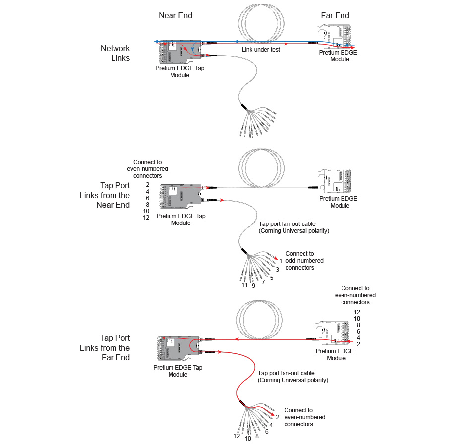
Figure 1. Three Paths for Loss Budget Calculations
Figure 2 shows an example of a loss budget calculation for a test from the far end through the tap port and through a fan-out cable. Note that the loss of the LC connection at the end of the fan-out cable is not included in this example.
The calculation includes the loss of a 600 m trunk fiber and a 10 m tap port fan-out cable:
-
Loss for 600 m of OM4 EDGE trunk fiber for a network link:
2.8 dB/km x .6 km = 1.68 dB -
Loss for 10 m of OM4 EDGE trunk fiber for a tap port harness:
2.8 dB/km x .01 km = 0.028 dB
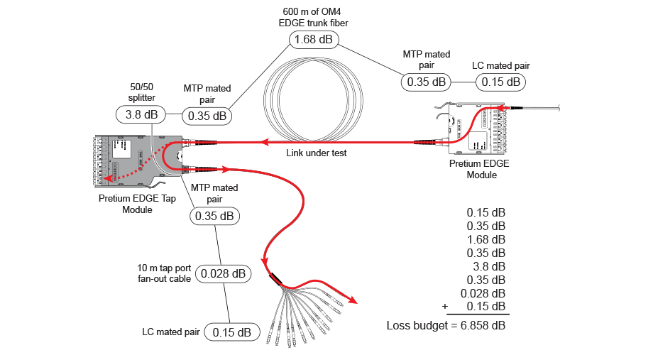
Figure 2. Example of a Loss Budget Calculation for Testing Network Links
For more examples of loss budget calculations, see the Corning Standard Recommended Procedure (SRP) document number 003-126 on the Corning web site.
Setting Up a Custom Test Limit
Next, make a custom test limit that will include your loss budget values and do tests only at 850 nm. The first loss budget value you enter will be for the first network link you will test.
1. On the home screen, tap the test setup panel.
2. On the CHANGE TEST screen, tap a CertiFiber Pro test, then tap EDIT.
3. On the TEST SETUP screen, tap Test Limit, tap MORE, tap Custom, the tap MANAGE.
4. On the MANAGE CUSTOM screen, tap the Create panel.
5. On the NEW CUSTOM LIMIT screen, tap Enter New Limit Name, use the keyboard to enter a name, then tap DONE.
6. On the NEW CUSTOM LIMIT screen, enter these settings:
- Max lenth: Enter a value that is longer than the longest trunk in the fiber network.
- Loss Budget: Select Fixed.
- Wavelength specific settings: For Overall Loss @ 850 (dB), enter the calculated budget for the first network link you will test. Note that if the network links are different lengths, you will need to change this value accordingly before you test each link.
- Leave the Overall Loss for all other wavelengths as N/A.
7. Tap SAVE.
8. One the TEST LIMIT screen, tap ![]() twice to go back to the TEST SETUP screen.
twice to go back to the TEST SETUP screen.
9. Tap TEST LIMIT, tap MORE, tap Custom, then tap the custom limit you made.
10. On the TEST SETUP screen, enter these settings:
- Test Type: Smart Remote
- Bi-Directional: Off
- Fiber Type: Select a fiber type that is correct for the type you will test.
- Reference Method: 1 Jumper. This is the number of jumpers you will use in each fiber path when you set the reference.
- Connector Type: Select MPO Module. The tester saves this setting to record the type of connector you used. This setting does not change your test results or any of the diagrams that the tester shows.
- No. of MPO Modules/Splices: The Total MPO Modules and Splices settings do not apply because you are using a fixed loss budget. Jumper Reference is 1.
11. On the TEST SETUP screen, tap SAVE.
Testing the Network Links
The network links are duplex connections, so you use Smart Remote mode to test both fibers in each link.
Set the Reference for Smart Remote Mode
- Turn on the tester and remote and let them sit for a minimum of 5 minutes. Let them sit longer if they are above or below ambient temperature.
- Clean and inspect the connectors on the tester, remote, and test reference cords.
- On the home screen tap SET REF.
- On the SET REFERENCE screen, tap RUN WIZARD. Note: To only set the reference, and not measure the loss of your test reference cords, tap SKIP WIZARD on the SET REFERENCE screen.
- Make the connections to set the reference, as shown on the screen and in Figure 3, then tap NEXT to see the completed connections.
- To enter the length of the test reference cords you will add to connect to the link, tap TRC LENGTH on the SET REFERENCEscreen. The length you enter does not change the test results. The tester saves the length with the results to meet TIA reporting requirements.
- Tap SET REFERENCE. If you did not use the connection wizard, go to “Test the Network Links in Smart Remote Mode” on page
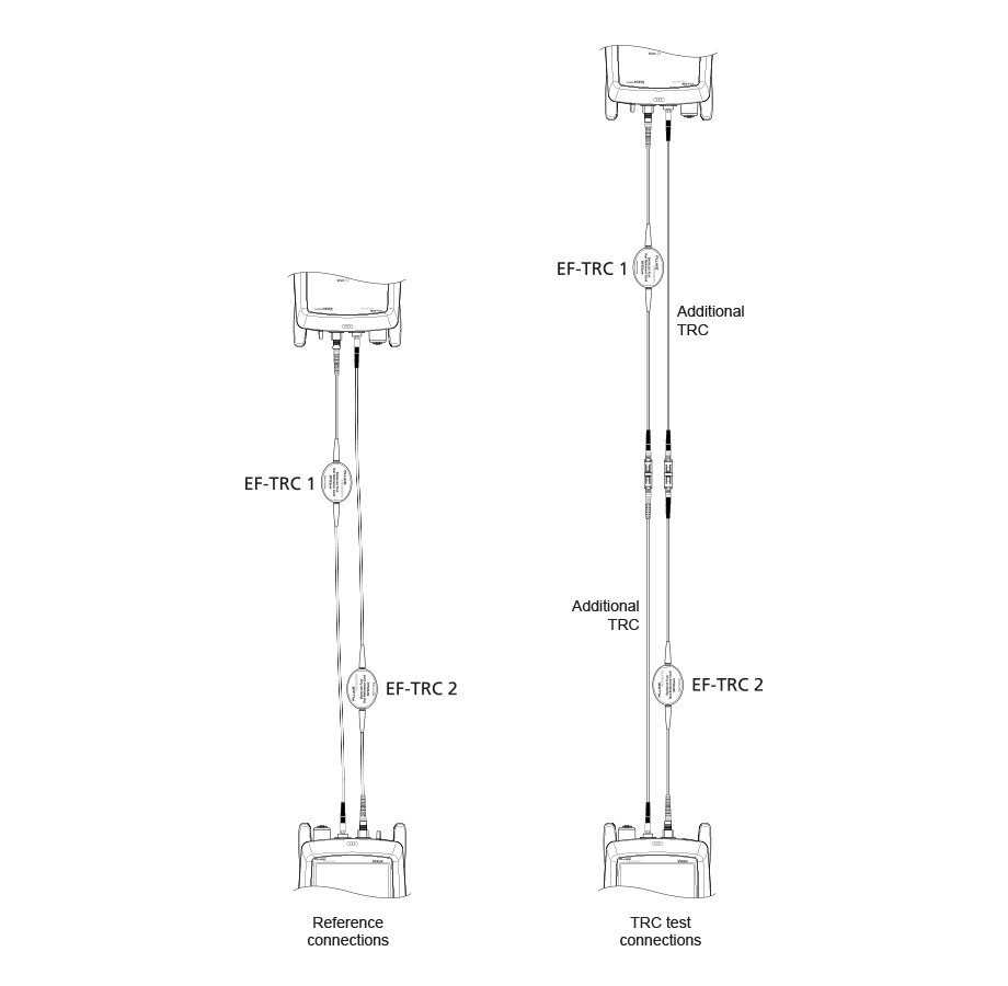
Figure 3. Reference and TRC Test Connections for Smart Remote Mode
Next, if you used the connection wizard, verify that the test reference cords (TRCs) you will add are good:
1. On the SET REFERENCE screen, when the reference procedure is completed, tap NEXT.
2. Disconnect the test reference cords from the INPUT ports on the tester and remote, then use test reference cords and adapters to make the connections to verify the TRCs, as shown on the screen and in Figure 3.
3. Tap TRC VERIFICATION. The tester measures and saves the loss of the test reference cords you added. The IDs for these results start with “TRC”, show the date and time of the test, and have an ![]() for the test result. The tester shows a warning if the loss of a TRC is more than 0.15 dB. If the tester shows a warning, clean and inspect the connectors on the TRCs in the path that has too much loss, then set the reference and do the TRC verification again.
for the test result. The tester shows a warning if the loss of a TRC is more than 0.15 dB. If the tester shows a warning, clean and inspect the connectors on the TRCs in the path that has too much loss, then set the reference and do the TRC verification again.
Test the Network Links in Smart Remote Mode
1.Clean and inspect the LC connectors on the EDGE Tap and EDGE modules.
2. Connect the TRCs to the near and far ends of the links, as shown in Figure 4.
3. Press B.
4. If the test passes, save the results. If it fails, clean and inspect the connections again, or troubleshoot as necessary, then test again.
5. If the network links are different lengths, change the value for the Overall Loss @ 850 (dB) in your custom limit to the applicable loss budget value for the next link. (TEST SETUP screen > Edit > Test Limit > MORE > Custom > MANAGE > Edit.)
6. Repeat steps 2-5 for all the links.
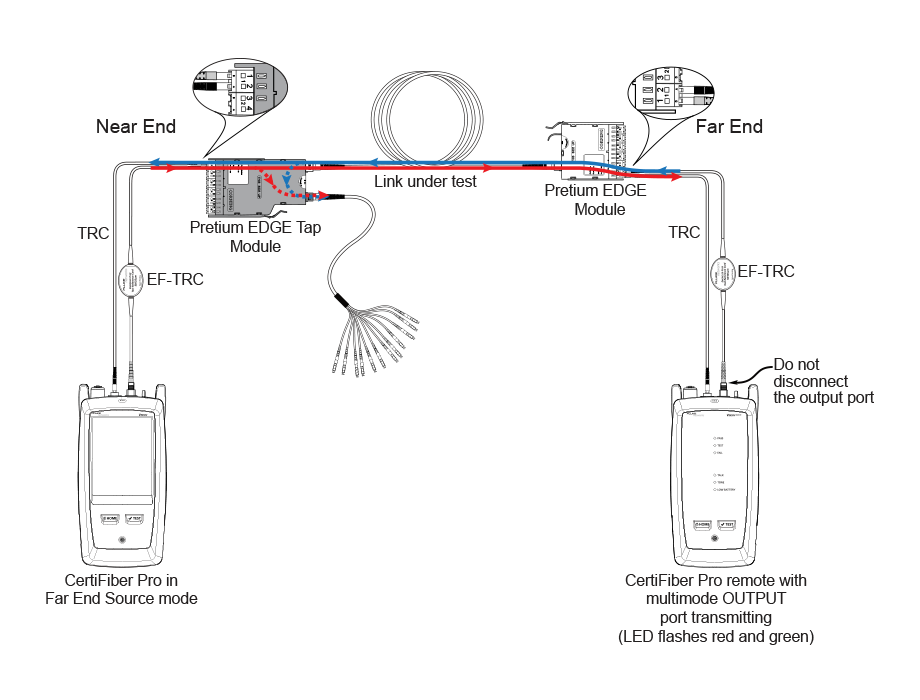
Figure 4. Connections for Testing the Network Links
Testing the Tap Port Links
It’s not necessary to test the tap port links to meet Corning’s requirements for warranty coverage, but you may want to do so to make sure your tap port links are good.
Note that this article shows the TAP port connected to a Corning Universal polarity fan-out cable. You can also connect the TAP port to another Pretium EDGE module. In that case, you would add another MTP and LC mated pair loss to your loss budget, and you would connect the CertiFiber Pro tester to the LC ports in the module.
TAP Port Connections
When you connect the remote to the EDGE Tap module at the near end, you measure the tap port link’s loss at the odd-numbered connectors on the tap port fan-out cable or EDGE module connected to the tap port. When you connect the remote to the EDGE module at the far end, you measure the tap port link’s loss at the even-numbered connectors on the tap port fan-out cable or EDGE module connected to the tap port. Figure 5 shows these connections.
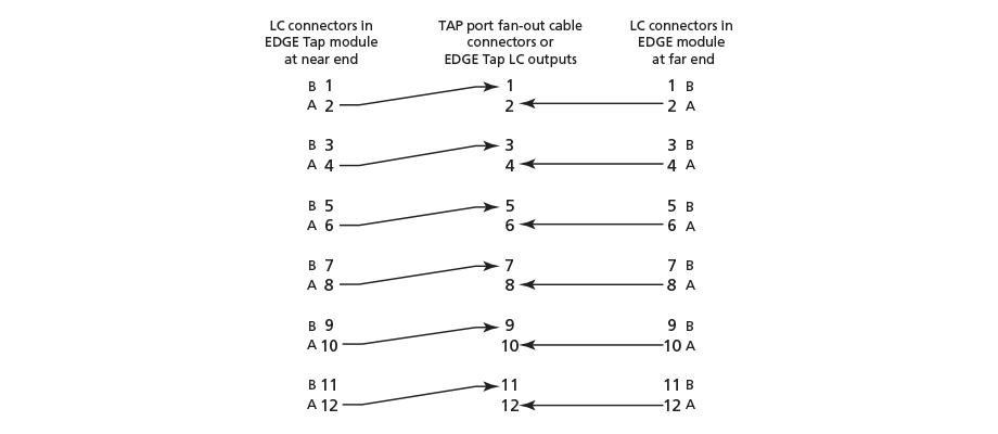
Figure 5. Connections from the Near and Far End Modules to the TAP Port Cable
Set the Reference for Far End Source Mode
Because all of the tap port connections are outputs, you will use Far End Source mode to test all the tap port links in the same direction, one at a time. Set the reference and test your test reference cords (TRCs) as follows:
1. Turn on the tester and remote and let them sit for a minimum of 5 minutes. Let them sit longer if they are above or below ambient temperature.
2. Clean and inspect the connectors on the tester, remote, and test reference cords.
3. On the home screen, tap the test setup panel.
4. On the CHANGE TEST screen, tap the CertiFiber Pro test you set up before, then tap EDIT.
5. On the TEST SETUP screen tap Test Type, the tap Far End Source:
6. On the TEST SETUP screen, tap SAVE.
7. On the home screen tap SET REF.
8. In the TEST SETUP screen, tap SAVE.
9. On the SET PREFERENCE screen, tap RUN WIZARD. Note: to only SKIP WIZARDTo only set the reference, and not measure the loss of your test reference cords, tap the SET REFERENCE screen.
10. Make the connections to set the reference, as shown on the screen and in Figure 6, then tap NEXT to see the completed connections.
11. To enter the length of the test reference cords you will add to connect to the link, TRC LENGTH and the SET REFERENCEscreen. The length you enter does not change the test results. The tester saves the length with the results to meet TIA reporting requirements.
12. On the CertiFiber Pro remote module, hold down the button adjacent to the VFL port for 3 seconds to turn on the multimode source.
13. Tap SET REFERENCE.
14. If you did not use the connection wizard, go to “Test the Tap Port Links from the Near End” on page 13.
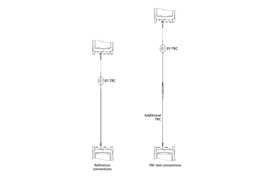
Figure 6. Reference and TRC Test Connections for Far End Source Mode
Next, if you used the connection wizard, verify that the test reference cord (TRC) you will add is good:
1. On the SET PREFERENCE screen, when the reference procedure is completed, tap NEXT.
2. Disconnect the test reference cord from the INPUT port on the tester, then use a test reference cord and adapter to make the connections to verify the TRCs, as shown on the screen and in Figure 6.
3. Tap TRC VERIFICATON. The tester measures and saves the loss of the test reference cord you added. The ID for this results start with “TRC”, show the date and time of the test, and have an ![]() for the test result. The tester shows a warning if the loss of a TRC is more than 0.15 dB. If the tester shows a warning, clean and inspect the connectors on the TRC, then set the reference and do the TRC verification again.
for the test result. The tester shows a warning if the loss of a TRC is more than 0.15 dB. If the tester shows a warning, clean and inspect the connectors on the TRC, then set the reference and do the TRC verification again.
Test the Tap Port Links from the Near End
1. Change the value for the Overall Loss @ 850 (dB) in your custom limit to the applicable loss budget value for the fiber path from the near end through the tap port. (TEST SETUP screen > Edit > Test Limit > MORE > Custom > MANAGE > Edit.)
2. Clean and inspect the even-numbered LC connectors on the EDGE Tap module (near end) and the odd-numbered connectors on the tap port fan-out cable or third EDGE module.
3. Make the connections shown in Figure 7 if you will do the test through a fan-out cable, or in Figure 8 if you will do the test through a third EDGE module.
4. If necessary, select End 1 or End 2. On the home screen, tap the Next ID: pnael, them tap the End 1/End 2 control to select an end.
5. Tap TEST on the main tester or press B on the main or remote tester.
6. If the test passes, save the results. If it fails, clean and inspect the connections again, or troubleshoot as necessary, then test again.
7. Repeat steps 3-6 for all tap port links.
Note: To put End 1/End 2 results together in the same record, use LinkWare software to merge the results.
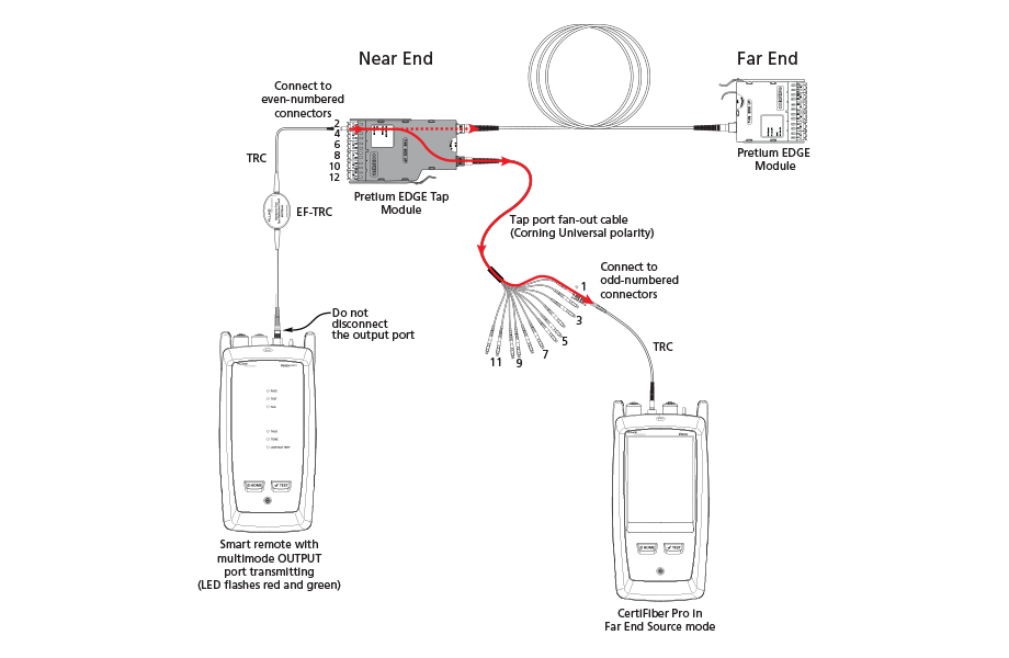
Figure 7. Connections for Testing the Tap Port Links
from the Near End through a Fan-Out Cable
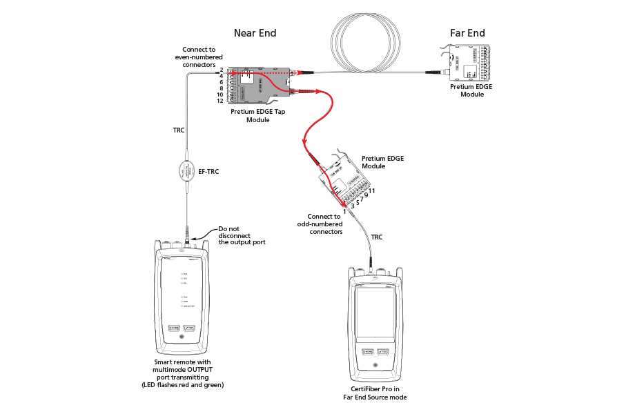
Figure 8. Connections for Testing the Tap Port Links
from the Near End through an EDGE Module
Test the Tap Port Links from the Far End
1. Change the value for the Maximum Loss at 850 nm in your custom limit to the applicable loss budget value for the first tap port link you will test from the far end through the tap port.
2. Clean and inspect the even-numbered LC connectors on the EDGE module (far end) and the even-numbered connectors on the tap port fan-out cable or third EDGE module.
3. Make the connections shown in Figure 9 if you will do the test through a fan-out cable, or in Figure 10 if you will do the test through a third EDGE module.
4. If necessary, select End 1 or End 2. On the home screen, tap the Next ID: panel, then tap the End 1/End 2 control to select an end.
5. Tap TEST on the main tester or press B on the main or remote tester.
6. If the test passes, save the results. If it fails, clean and inspect the connections again, or troubleshoot as necessary, then test again.
7. If the network links are different lengths, change the value for the Maximum Loss at 850 nm in your custom limit to the applicable loss budget value for the next tap port link.
8. Repeat steps 3-7 for all the tap port links.
Note:To put End 1/End 2 results together in the same record, use LinkWare software to merge the results.
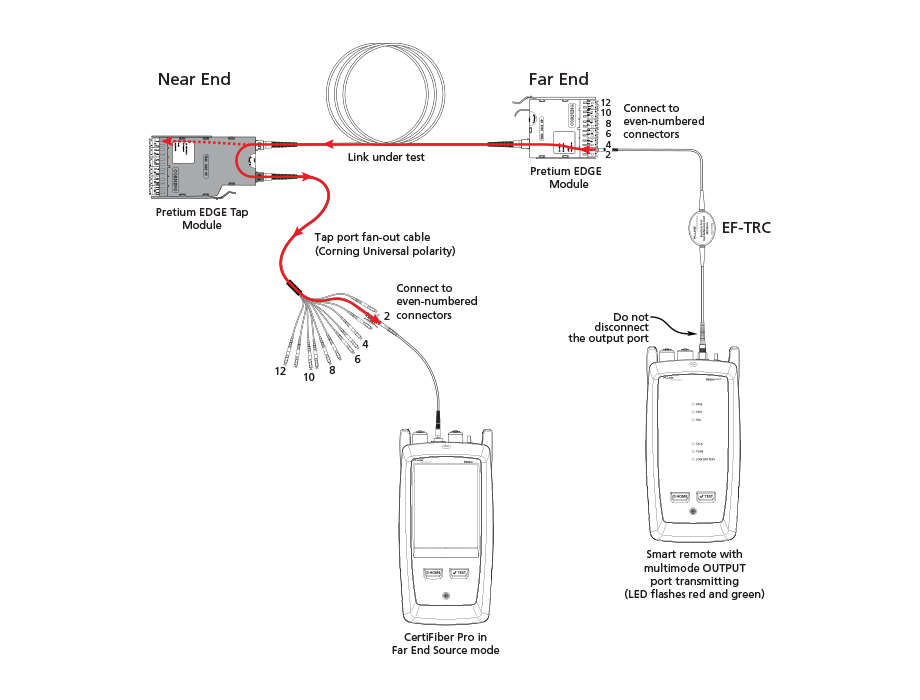
Figure 9. Connections for Testing the Tap Port Links
from the Far End through a Fan-Out Cable
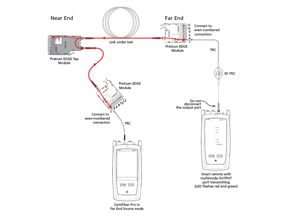
Figure 10. Connections for Testing the Tap Port Links
from the Far End through an EDGE Module


