Overview Four Pair Power Over Ethernet (PoE)
For several years, you’ve been deploying cable plants that support power over Ethernet (PoE) for variety of devices like VoIP phones and security cameras. So far, up to 30 Watts is all you’ve been requested to support, but with the plethora of devices now able to take advantage of higher levels of PoE—like the latest 802.11ac Wi-Fi access points, digital displays and even desktop computers—your customers are starting to ask for four-pair PoE. This article provides an update on four PoE-related topics: the proposed standards, cabling requirements, LP cabling certification, and field-terminated plugs.
On This Page
Four Pair Power Over Ethernet (PoE) and Your Cabling Plant
For several years, you’ve been deploying cable plants that support power over Ethernet (PoE) for variety of devices like VoIP phones and security cameras. So far, up to 30 Watts is all you’ve been requested to support, but with the plethora of devices now able to take advantage of higher levels of PoE—like the latest 802.11ac Wi-Fi access points, digital displays and even desktop computers—your customers are starting to ask for four-pair PoE. This article provides an update on four PoE-related topics: the proposed standards, cabling requirements, LP cabling certification, and field-terminated plugs.
The Standards
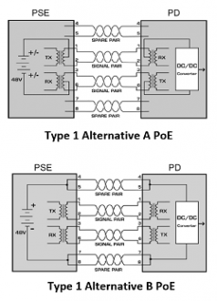
Let’s start with the differences between the existing types of PoE. Type 1 PoE delivers up to 15.4 W, with 13 W available for the device, and Type 2 PoE (sometimes referred to as PoE Plus) delivers up to 30 W, with 25.5 W available for the device. Both deliver power over two pairs using one of two methods—Alternative A and Alternative B.
In Alternative A, power is delivered simultaneously with data over pairs 1-2 and 3-6. In Alternative B, power is delivered over spare pairs 4-5 and 7-8. While Alternative A is compatible with both two-pair (such as 10/100BASE-T) and four-pair (such as 1000BASE-T) applications, Alternative B is only compatible with data signals that use two pairs.
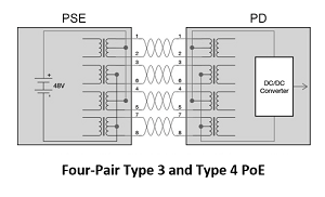
The 802.3bt standard for four-pair PoE includes Type 3 and Type 4, both of which now deliver power over all four pairs simultaneously with data. Type 3 PoE delivers up to 60W, with 51W available for the device, while Type 4 delivers up to 90W, with 71W available for the device.
Ethernet Alliance Certification Program
To enhance interoperability, the Ethernet Alliance, a consortium of manufacturers representing providers of ninety percent of PSE switching equipment, has announced a PoE Certification Program. This program provides a methodology for certifying their products for interoperability with other IEEE-802.3-based PoE solutions and provides simple labeling of such products.
Certification of the products is defined by a 300-page test plan, using approved equipment. This may be conducted by manufacturers or third parties, such as the University of New Hampshire’s Interoperability Laboratory (UNH-IOL). Both PSE and PD equipment may be certified. Equipment that passes this rigorous process may be labeled with the EA approved marks as shown.
Designers or installers of PoE equipment can simply compare the marks on the PSE and PD to determine compatibility. If the rating of the PSE is equal to or higher than the requirements of the PD, functionality is assured.

Ethernet Alliance marks for Powered Devices (left) and Power Sourcing Equipment (right).
Cabling Requirements
In Type 1 and Type 2 PoE using Alternative A, power is transmitted by applying a common-mode voltage on the two pairs—meaning the current is evenly split between the two conductors. For this to happen, the DC resistance of each conductor in the pair must be balanced (equal), and any difference is referred to as DC resistance unbalance. Too much unbalance can distort data signals, causing bit errors, retransmits and even nonfunctioning data links.
Like Type 1 and Type 2 PoE Alternative A, four-pair Type 3 and Type 4 PoE also deliver power via common-mode voltage, so DC resistance unbalance matters here as well. However, in Type 3 and Type 4, it is no longer just the DC resistance unbalance on each pair you need to worry about. Excessive DC resistance unbalance between multiple pairs can also wreak havoc on data transmission and cause PoE to stop working.
While poor quality cable with variations in conductor diameter and concentricity (roundness) are at a higher risk of DC resistance unbalance, inconsistent terminations where individual conductors are not properly and consistently seated within IDCs can also cause DC resistance unbalance. So while you may see a DC resistance unbalance specification on a vendor’s cable, field testing is really the only way to ensure DC resistance unbalance performance after installation.
The DSX CableAnalyzer™ Series can quickly and easily test DC resistance unbalance within a pair and between pairs, so you can rest assured that the cable plant you deploy will perform in two- and four-pair PoE applications.
Heat Rise and Limited Power Cabling
Unfortunately, DC resistance unbalance isn’t the only thing you need to worry about. When PoE is delivered over twisted-pair copper cabling, increased temperature within the cable can increase insertion loss. This can cause a channel to fail insertion loss testing or require the length of the cable to be reduced.
Heat generated by PoE is even more of an issue when multiple cables delivering PoE are together in a tight bundle—and the higher the power, the greater the heat. The National Electric Code specifies the number of cables allowed in a bundle based on conductor size and temperature rating for 60W or higher PoE. The TIA is also developing guidelines for limiting temperature rise in a bundle.
Following a fact-finding study to investigate the effects of higher levels of PoE applied over cables in a bundle, Underwriter’s Laboratories (UL) introduced a Limited Power (LP) Certification to help simplify cable choice for PoE applications. The LP certification indicates that a cable has been tested to carry PoE under worst-case installation scenarios without exceeding the temperature rating of the cable. The certification accounts for large bundle sizes, high ambient temperatures and other environmental effects such as enclosed spaces or conduits.
It’s important to understand that LP is a certification, not a listing or a rating. So unlike other UL listings or plenum or riser ratings that are required by the NFPA 70 National Electric Code®, LP-certified cable is an option—not a requirement. And speaking of the NEC®, the 2017 edition contains new requirements that also address the heat rise issue—but only when power is greater than 60W (Type 3). For these cases, NEC includes ampacity tables that specify the maximum ampacity allowed for a certain cable bundle size, conductor gauge and cable temperature rating installed in an ambient temperature of 30°C (86°F). Because the NEC® is law, complying with these ampacity tables is required. However, the NEC does allow the use of an LP-certified cable as an alternative to following the ampacity table.
The good news is that you only need to worry about this issue if you’re planning to run PoE above 60W, and most PoE-enabled devices, including LED lights, require less than that. The bad news is that you never really know how much power might eventually be delivered over the cable so following ampacity tables or using LP-certified cable is a good method for future proofing. Other options include using cables with larger diameter conductors, higher temperature ratings or shielded construction, as well as simply choosing to not use cable bundles.
While DC resistance unbalance is not typically an issue in higher quality cables that would have a higher temperature rating or LP certification, poor workmanship can still cause too much resistance unbalance. Therefore, it is still recommended that LP cabling be tested for DC resistance.
Modular Plug Terminated Links
 With the Internet of Things (IoT) and the development of sensor technology, more and more devices are becoming IP enabled and connecting to the copper horizontal cabling infrastructure. Most of these devices such as LED lights, security cameras, building automation controls, and Wi-Fi access points include an integrated RJ45 port for connecting to the network.
There may be scenarios where a typical four-connector channel is not used when connecting these types of devices– especially those that reside in the ceiling space where it is impractical to install a faceplate. Instead, there is just one patch cord in the telecommunications room and the permanent link is terminated at the other end with a plug so it can plug directly into the device, essentially eliminating the equipment cord. This creates what is now known as a Modular Plug Terminated Link, or MPTL, and as this application becomes more common and shows up in industry standards, it’s good to get a handle on how to test it today.
Some of the benefits of using a plug-terminated link include improved security and aesthetics by avoiding exposed patch cords that can be inadvertently or deliberately disconnected (think of a security camera) and the ability to adhere to the code requirement of only placing plenum-rated products in air-handling spaces (not all patch cords are plenum rated).
The use of a link that terminates to a plug and eliminates the equipment cord was first called out in the BICSI 005 Electronic Safety and Security standard and appears again in the BICSI 033 Information Communication Technology Design and Implementation Practices for Intelligent Buildings and Premises targeted for publication later this year. The TIA-862 Building Automation Standard also recognizes the need to eliminate an equipment cord when deemed unfeasible or unsafe and specifically allows for the use of a plug-terminated link. This application was originally referred to as a “direct attach connection” but due to confusion with direct attach connections used in data center switch-to-server applications, the terminology has evolved.
While recognized by industry standards as an application, there were previously no specific test requirements for a plug-terminated link specified by the TIA. Hence, as recommended by BICSI, these connections were originally tested using Modified Single-Connector Permanent Link testing. This was achieved by attaching the main testing unit at the patch panel with a Permanent Link Adapter, attaching the remote unit at the far end with a Channel Adapter and choosing the “Mod 1-Conn Perm. Link” application on the tester. The problem with using a Channel Adapter at the far end is that the mated connection at the far end was excluded from the test.
With the proliferation of field-terminated plugs, and the potential for a poor plug termination, standards bodies have recognized the need for a test procedure that includes the final plug connection at the far end. The current draft of the ANSI-TIA568.2-D standard includes the MPTL configuration and this test is already integrated into the DSX CableAnalyzer Series.
Installation Tools
 Even with a properly certified cabling plant, technicians installing PoE will run into issues. Maybe the cable has been mislabeled, broken, connected to the wrong port or disconnected entirely. Or the switch may not be configured to deliver adequate power. Troubleshooting these problems can take hours of time if the technician can’t see what’s on the wire. Then they have to trace the wire find out if it’s OK, and where it’s connected. And even if they figure that out, they can’t tell by looking at the switch if the power is configured correctly. Then they’ll need to contact IT to figure out what’s going on.
Fluke Networks has developed two tools to solve these problems and save the tech hours of frustration: The LinkIQ™ Cable+Network Tester and the MicroScanner™ PoE. Simply plug either tool into the cable, and if it’s connected to a PSE, it will display the class (0-8) of power available on the link. The tech can then compare that to the requirements of the PD and know if sufficient power will be available. The LinkIQ performs a further test by placing a load on the PSE to determine if the switch and cabling link are capable of delivering the advertised power. The MicroScanner™ PoE has successfully completed the Ethernet Alliance Gen2 PoE Certified program test plan, providing confidence that it will work properly with all IEEE-compliant devices. The tester is also designed to work with a wide variety of non-IEEE-compliant technologies, but since there’s no certification program for that, you’ll just have to take our word for it.
These testers are invaluable to the tech in many other ways. They will identify the speed of the port up to 10 Gbps. A slow port may limit the performance of an access point or camera. If the cable has been damaged, they display the length of each pair, potential breaks or other failures. Cables can also be unplugged or misrouted – so these testers can act as a tone source for tracing the cable. Identifiers can be connected to remote cables to determine where they go. The LinkIQ offers additional features: characterizing the performance of the cabling up to 10 Gb/s, displaying the name, port and VLAN number of a connected switch. Finally, the LinkIQ can generate reports for the cabling or the switch and store or print them using the popular LinkWare™ PC software.
Pick the right equipment, certify the cable’s capable and then make sure your tech can check and troubleshoot the installation and your PoE project will go smoothly.

LinkIQ Cable+Network Tester
Contact Us
U.S. / Canada: 1-800-283-5853
International: 1-425-446-4519
info@flukenetworks.com
Gold Maintenance and Support Program
Related Products

LinkIQ™ Cable + Network Tester
DSX CableAnalyzer™ Series Copper Cable Certifiers
MicroScanner™ Cable Verifier Series


