Get Back to Cabling Basics If Anything Goes Wrong
February 25, 2016 / General, 101 learning, Installation and testing, Upgrading and troubleshooting, Best Practices
How we communicate and share information today is all done via networks, and every day our world becomes more connected. The Internet of Things (IoT) is placing more IP-based devices on the network than ever before--from digital displays and LED lighting, to security apparatus and building automation systems.
 With everything from personal banking, booking vacations and watching videos, to the business of managing facilities, securing perimeters and completing customer transactions now done from the comfort of a desktop, many of us expect and assume that the network will always be up and running.
But if you're responsible for your company's network infrastructure, it's better to think along the lines of "If anything can go wrong, it probably will." The majority of network failures and downtime are caused by issues at the physical layer, and many of these problems occur at the very basic level, which often get disregarded as the cause.
Sometimes it's necessary to get back to basics.
Wiring Scheme & Split Pairs
While the pin/pair assignments for twisted-pair copper cabling per TIA/EIA-568 standards may not even be on your radar as a network problem, getting the 568A and 568B wiring schemes mixed up or completely wrong is a more common problem than one might think--especially when non-datacom installers take on terminations. This is a common problem in patch cords, where someone has decided to make their own without knowledge of pairing sequences.
While it may seem logical to terminate pairs as 1-2, 3-4, 5-6 and 7-8, the standards require one those pairs to be divided on pins 3-6 as Pair 2 for 568A or as Pair 3 for 568B (an outcome of having pair 4-5 used for legacy telephone). Either 568A or 568B may be used, but both ends of the permanent link must be wired using the same scheme. If you mix up the wiring schemes 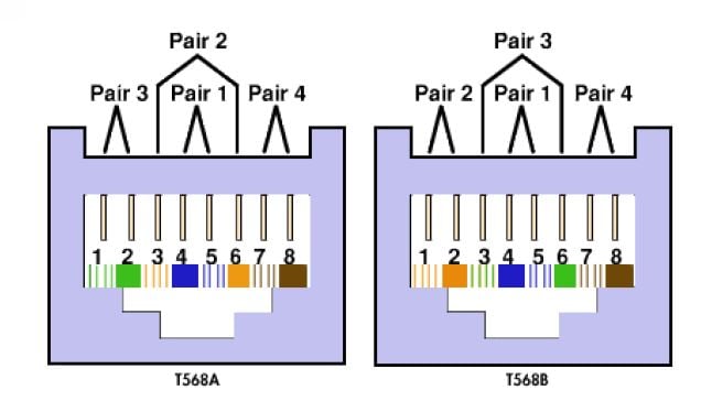 you'll end up with crossed pairs. If you don't realize the need to treat pins 3-6 as a pair, you'll end up with split pairs.
Split pairs cause interference such as crosstalk and signal delay between pairs (i.e., skew) that can impact data/voice/video transmission. Split pairs are also one of the more difficult problems to detect because some inexpensive wire map testers that only check for DC continuity will pass the test. But simple continuity between pins from one end of the cable to the other is not sufficient for reliable high speed data and video services.
Make sure you have a wire map tester that goes beyond a simple continuity test to ensure that each connector pin from one end of the link is connected to the corresponding pin at the far end to maintain uninterrupted pairing over the total length of the link. Fluke Networks's CableIQ Qualification tester features intelligent wire map tests for length, crosstalk, shorts, split pairs, or opens and displays with an intuitive graphical interface where a fault is located.
Poor Quality Cables and Connections

Another basic and common problem comes down to quality. First of all, the cables and connectors you select should come from a reputable manufacturer. To properly support the application, you need to be 100% certain that the components have been tested and properly validated to comply with the performance standards for that cable.
Sometimes a quality issue isn't related to the manufacturer or supplier. Take fiber for example. You can never assume that a fiber end face is clean, even when it comes out of a sealed package. In fact, end caps are one of the biggest reservoirs for dust and dirt. They are intended to protect the fiber, not keep it clean. And anytime you connect a dirty fiber end face, you risk cross contamination.
Again, beware of the limitations of your tester. While a visual fault locator (VFL) will indicate that light is getting from one end to the other, this is all it will tell you. You might be missing a contaminated fiber connection that can cause reflectance and an increased Bit Error Rate. Instead, using Fluke Networks' CertiFiber Pro Optical Loss Test Set (OLTS) will help you determine if there is too much loss in a fiber link.
Better yet, make sure to clean and inspect each fiber end face before connecting. Fluke Networks’ FI-7000 FiberInspector Pro can inspect and certify fiber end faces to IEC 61300-3-35 standards that certify the cleanliness of a fiber end face based on the number and size of scratches and defects found in each region of the end face.
And remember that if anything can go wrong, it probably will. Don't forget to consider some of the very basic issues that can cause problems with your cabling infrastructure--they are more often the problem than you might think.
Recent Posts See All >
What Is Fiber Optics? A Guide
2024-03-20
Choosing Stranded vs. Solid Wire Cable
2024-03-06
What Is Return Loss?
2023-02-14
More General Posts See All >
What Is Fiber Optics? A Guide
2024-03-20
Choosing Stranded vs. Solid Wire Cable
2024-03-06
What Is the Right Way to Test an MPTL?
2023-08-22


©2006-2021 Fluke Corporation。保留所有权利。
RM2011, 20/F, SCITECH Tower, 22 Jianguomenwai Avenue, Chaoyang District, Beijing, China
地址:北京市朝阳区建国门外大街22号赛特大厦20层2011室
联系电话:400-8103435
沪ICP备11037028号-15![]()